H89KPN SCR Spec
H89KPN ELECTRICAL SPECIFICATIONS
Type: SCR
Maximum peak gate power (PGM): 0.1 W
Maximum repetitive peak and off-state voltage (VDRM): 300 V
Maximum average on-state current (IT(AVR)): 0.5 A
Maximum RMS on-state current (IT(RMS)): 0.8 A
Critical repetitive rate of rise of on-state current (dI/dt): 30 A/µs
Critical rate of rise of off-state voltage (dV/dt): 25 V/µs
Maximum operating junction and storage temperature range (Tstg, Tj): -40..125 °C
Junction to ambient thermal resistance (RTH(j-a)): 200 K/W
Junction to case thermal resistance (RTH(j-c)): 100 K/W
Triggering gate voltage (VGT): 0.8 V
Triggering gate current (IGT): 0.2 mA
Holding current (IH): 5 mA
Package: SOT‑89
H89KPN Spec
Page #1
Page #2
Description
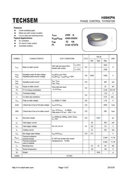
H89KPN PHASE CONTROL THYRISTOR Features Center amplifying gate Metal case with ceramic insulator IT(AV) 2300 A Low on-state and switching losses Typical Applications VDRM/VRRM 4500-5500V AC controllers ITSM 32 kA DC and AC motor control I2t 5120 103A2S Controlled rectifiers VALUE SYMBOL CHARACTERISTIC TEST CONDITIONS Tj(C) UNIT Min Type Max TC=55C 2820 180 half sine wave 50Hz IT(AV) Mean on-state current 125 A Double side co


