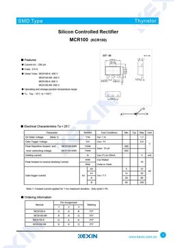
KCR100-8 Triac Spec
KCR100-8 ELECTRICAL SPECIFICATIONS
Type: Triac
Maximum repetitive peak and off-state voltage (VDRM): 600 V
Maximum average on-state current (IT(AVR)): 0.9 A
Maximum RMS on-state current (IT(RMS)): 1 A
Non repetitive surge peak on-state current (ITSM): 12 A
Critical rate of rise of off-state voltage (dV/dt): 10 V/µs
Maximum operating junction and storage temperature range (Tstg, Tj): -40..125 °C
Junction to ambient thermal resistance (RTH(j-a)): 150 K/W
Junction to case thermal resistance (RTH(j-c)): 48 K/W
Triggering gate voltage (VGT): 1.5 V
Peak on-state voltage drop (VTM): 1.6 V
Triggering gate current (IGT): 5 mA
Holding current (IH): 5 mA
Package: SOT‑223
KCR100-8 Spec
Page #1
Page #2
Description
SMD Type Thyristor Silicon Controlled Rectifier MCR100 (KCR100) ■ Features 1.70 0.1 ● Current-IGT : 200 μA ● ITRMS : 0.8 A. ● VRRM/ VDRM : MCR100-6: 400 V MCR100-6R: 400 V 0.42 0.1 MCR100-8: 600 V 0.46 0.1 MCR100-8R: 600 V ● Operating and storage junction temperature range ● TJ,Tstg : -55℃ to +150℃ ■ Electrical Characteristics Ta = 25℃ Parameter Symbol Test Conditions Min Typ Max Unit On State Voltage (Note.1) VTM ITM= 1 A 1.7 Gate Trigger Vol


