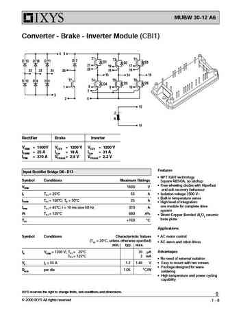
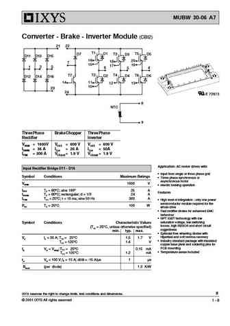
MUBW35-12A7 IGBT Equivalente. Reemplazo. Hoja de especificaciones. Principales características
Número de Parte: MUBW35-12A7
Tipo de transistor: IGBT
Polaridad de transistor: N
ESPECIFICACIONES TECNICAS
Pcⓘ - Máxima potencia disipada: 120 W
|Vce|ⓘ - Tensión máxima colector-emisor: 1200 V
|Ic|ⓘ - Colector de Corriente Continua a 25℃: 50 A
CARACTERÍSTICAS ELÉCTRICAS
|VCEsat|ⓘ - Voltaje de saturación colector-emisor, typ: 2.6 V @25℃
Encapsulados: MODULE
Búsqueda de reemplazo de MUBW35-12A7 IGBT
- Selección ⓘ de transistores por parámetros
MUBW35-12A7 datasheet
mubw35-12a7.pdf
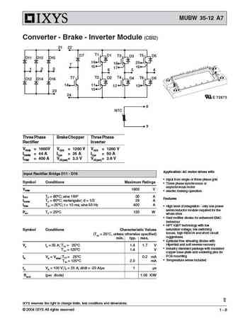
MUBW 35-12 A7 Converter - Brake - Inverter Module (CBI2) 21 22 T1 D1 T5 D7 T3 D5 D3 D11 D13 D15 16 20 18 7 15 19 17 1 2 3 4 6 5 T7 T2 T4 T6 D2 D4 D6 D12 D14 D16 14 11 12 13 10 23 24 8 NTC 9 Three Phase Brake Chopper Three Phase Rectifier Inverter VRRM = 1600V VCES = 1200 V VCES = 1200 V IDAVM = 44 A IC25 = 35 A IC25 = 50 A IFSM = 400 A VCE(sat)= 2.3 V VC
mubw35-12a8.pdf
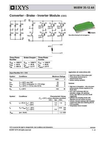
MUBW 35-12 A8 Converter - Brake - Inverter Module (CBI3) 21 22 T1 D1 T5 D7 T3 D5 D3 D11 D13 D15 16 20 18 7 15 19 17 1 2 3 4 6 5 T7 T2 T4 T6 D2 D4 D6 E72873 D12 D14 D16 See outline drawing for pin arrangement 14 11 12 13 10 23 24 8 NTC 9 Three Phase Brake Chopper Three Phase Rectifier Inverter VRRM = 1600 V VCES = 1200 V VCES = 1200 V IFAVM = 42 A IC25 =
mubw35-06a6k.pdf
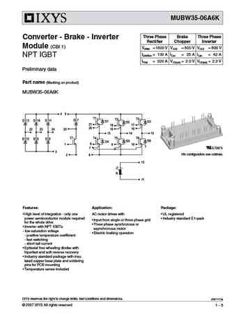
MUBW35-06A6K Three Phase Brake Three Phase Converter - Brake - Inverter Rectifier Chopper Inverter Module (CBI 1) VRRM = 1600 V VCES = 600 V VCES = 600 V IDAVM25 = 130 A IC25 = 25 A IC25 = 42 A NPT IGBT IFSM = 320 A VCE(sat) = 2.0 V VCE(sat) = 2.3 V Preliminary data Part name (Marking on product) MUBW35-06A6K E72873 Pin configuration see outlines. Features Application Package
mubw30-12a6k.pdf
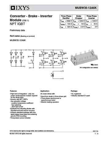
MUBW30-12A6K Three Phase Brake Three Phase Converter - Brake - Inverter Rectifier Chopper Inverter Module (CBI 1) VRRM = 1600 V VCES = 1200 V VCES = 1200 V IDAVM25 = 130 A IC25 = 19 A IC25 = 30 A NPT IGBT IFSM = 320 A VCE(sat) = 2.9 V VCE(sat) = 3 V Preliminary data Part name (Marking on product) MUBW30-12A6K E72873 Pin configuration see outlines. Features Application Package
Otros transistores... MUBW20-06A7 , MUBW25-06A6K , MUBW25-12A7 , MUBW25-12T7 , MUBW30-06A7 , MUBW30-12A6K , MUBW30-12E6K , MUBW35-06A6K , CRG40T65AK5HD , MUBW35-12A8 , MUBW35-12E7 , MUBW40-12T7 , MUBW45-12T6K , MUBW50-06A7 , MUBW50-06A8 , MUBW50-12A8 , MUBW50-12E8 .
🌐 : EN ES РУ
Liste
Recientemente añadidas las descripciónes de los transistores
IGBT: JJT40N120SE | JJT40N120HE | JJT30N65UE | JJT30N65SY | JJT30N65SS | JJT30N65SE | JJT40N65UH | JJT40N65UE | JJT40N65LE | JJT40N65HE | JJT40N135UE
Popular searches
c2389 transistor | c2634 transistor | mdp1991 datasheet | 40636 transistor | ao3407 datasheet | c1841 transistor | fb42n20d | irfb3306 equivalent
