AGM405AP2 MOSFET Equivalente. Reemplazo. Hoja de especificaciones. Principales características
Número de Parte: AGM405AP2
Tipo de FET: MOSFET
Polaridad de transistor: N
ESPECIFICACIONES MÁXIMAS
Pdⓘ - Máxima disipación de potencia: 28 W
|Vds|ⓘ - Voltaje máximo drenador-fuente: 40 V
|Vgs|ⓘ - Voltaje máximo fuente-puerta: 20 V
|Id|ⓘ - Corriente continua de drenaje: 46 A
Tjⓘ - Temperatura máxima de unión: 150 °C
CARACTERÍSTICAS ELÉCTRICAS
trⓘ - Tiempo de subida: 49.5 nS
Cossⓘ - Capacitancia de salida: 321 pF
RDSonⓘ - Resistencia estado encendido drenaje a fuente: 0.0059 Ohm
Encapsulados: PDFN3.3X3.3
Búsqueda de reemplazo de AGM405AP2 MOSFET
- Selecciónⓘ de transistores por parámetros
AGM405AP2 datasheet
agm405ap2.pdf

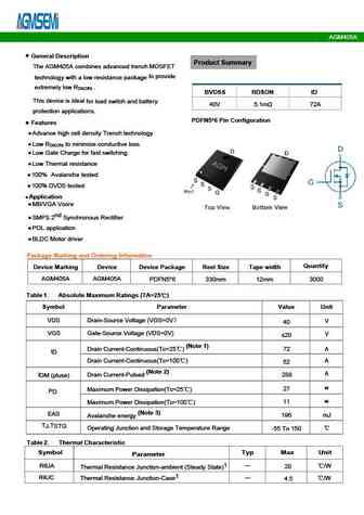
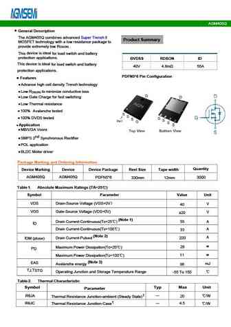
AGM405AP2 General Description Product Summary The AGM405AP2 combines advanced trench MOSFET to technology with a low resistance package provide extremely low R . DS(ON) BVDSS RDSON ID This device is ideal load switch and battery protection for 40V 4.4m 46A applications. PDFN3.3*3.3 Pin Configuration Features Advance high cell density Trench technology Low R t
agm405ap1.pdf

AGM405AP1 Table 3. Electrical Characteristics (TJ=25 unless otherwise noted) Symbol Parameter Conditions Min Typ Max Unit On/Off States BV Drain-Source Breakdown Voltage V =0V I =250 A 40 -- -- V GS D DSS Zero Gate Voltage Drain Current V =40V,V =0V -- -- 1 A DS GS I DSS Gate-Body Leakage Current V = 20V,V =0V -- -- nA GS DS I GSS 100 V Gate Threshold Voltage V =V ,I
agm405a.pdf
AGM405A Typical Performance Characteristics Figure 2 Typical Transfer Characteristics Figure1 Output Characteristics ID (A) ID (A) 150 100 5V 10V VDS=5V 4V 120 80 6V 3.5V 25 60 90 60 40 125 VGS=3V 30 20 VGS(V) VDS(V) 0 0 0 0.5 1.0 1.5 2.0 2.5 3.0 3.5 4.0 4.5 5.0 2 2.5 3 3.5 4 4.5 Figure 4 Body Diode Characteristics Figure 3 On-resistance vs. Drain Current I
agm405mbp.pdf

AGM405MBP Table 3. Electrical Characteristics (TJ=25 unless otherwise noted) Symbol Parameter Conditions Min Typ Max Unit On/Off States BVDSS Drain-Source Breakdown Voltage V =0V I =250 A GS D 40 -- -- V Zero Gate Voltage Drain Current V =40V,V =0V -- -- 1 A DS GS I DSS Gate-Body Leakage Current V = 20V,V =0V -- -- nA GS DS I GSS 100 VGS(th) Gate Threshold Voltage V

Otros transistores... HYG043N10NS2B , RM150N100HD , SLB40N26C , SLI40N26C , AGM404D , AGM404Q , AGM405A , AGM405AP1 , 13N50 , AGM405D , AGM405DG , AGM405F , AGM405MBP , AGM405MNA , AGM405Q , AGM406AP , AGM406MBP .
History: IRLR2905ZTR | WMO3N120D1 | MXP6018CT | IRFP257 | LPM4953 | LPM3400B3F | CS8N70FA9H2-G
History: IRLR2905ZTR | WMO3N120D1 | MXP6018CT | IRFP257 | LPM4953 | LPM3400B3F | CS8N70FA9H2-G
🌐 : EN ES РУ

Liste
Recientemente añadidas las descripciónes de los transistores:
MOSFET: AUB034N10 | AUB033N08BG | AUB026N085 | AUA062N08BG | AUA060N08AG | AUA056N08BGL | AUA039N10 | ASW80R290E | ASW65R120EFD | ASW65R110E | ASW65R095EFD | ASW65R046EFD | ASW65R041EFDA | ASW65R041E | ASW60R150E | ASW60R090EFDA
Popular searches
2sc897 | 2sa818 | 2sa763 | a933 | 2sa818 replacement | irfb3607 datasheet | 2n2907 equivalent | c2026