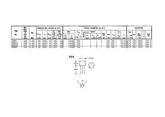
2N60A Equivalente. Reemplazo. Hoja de especificaciones. Principales características
Número de Parte: 2N60A
Material: Ge
Polaridad de transistor: PNP
ESPECIFICACIONES MÁXIMAS
Disipación total del dispositivo (Pc): 0.15 W
Tensión colector-base (Vcb): 40 V
Tensión emisor-base (Veb): 10 V
Corriente del colector DC máxima (Ic): 0.2 A
Temperatura operativa máxima (Tj): 85 °C
CARACTERÍSTICAS ELÉCTRICAS
Transición de frecuencia (ft): 0.6 MHz
Capacitancia de salida (Cc): 80 pF
Ganancia de corriente contínua (hfe): 70
Paquete / Cubierta: TO5
Búsqueda de reemplazo de 2N60A
2N60A datasheet
2n60a 2n60af 2n60g.pdf
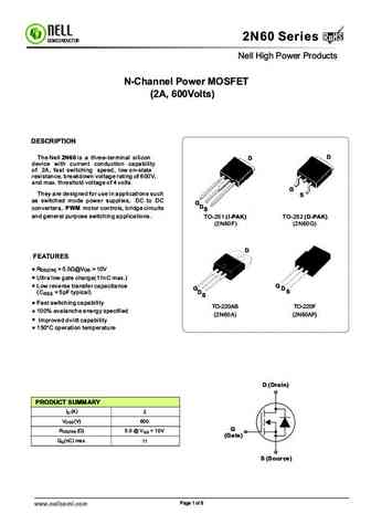
RoHS 2N60 Series RoHS SEMICONDUCTOR Nell High Power Products N-Channel Power MOSFET (2A, 600Volts) DESCRIPTION D The Nell 2N60 is a three-terminal silicon D device with current conduction capability of 2A, fast switching speed, low on-state resistance, breakdown voltage rating of 600V, and max. threshold voltage of 4 volts. G They are designed for use in applications such
hgtp12n60a4 hgtg12n60a4 hgt1s12n60a4s.pdf
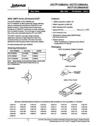
HGTP12N60A4, HGTG12N60A4, HGT1S12N60A4S Data Sheet May 1999 File Number 4656.2 600V, SMPS Series N-Channel IGBT Features The HGTP12N60A4, HGTG12N60A4 and >100kHz Operation at 390V, 12A HGT1S12N60A4S are MOS gated high voltage switching 200kHz Operation at 390V, 9A devices combining the best features of MOSFETs and 600V Switching SOA Capability bipolar transistors. These de
hgtg12n60a4d hgtp12n60a4d hgt1s12n60a4d.pdf
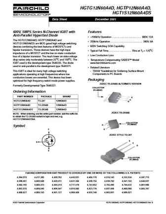
HGTG12N60A4D, HGTP12N60A4D, HGT1S12N60A4DS Data Sheet December 2001 600V, SMPS Series N-Channel IGBT with Features Anti-Parallel Hyperfast Diode >100kHz Operation . . . . . . . . . . . . . . . . . . . . . 390V, 12A The HGTG12N60A4D, HGTP12N60A4D and 200kHz Operation . . . . . . . . . . . . . . . . . . . . . . . 390V, 9A HGT1S12N60A4DS are MOS gated high voltage switching
hgtg12n60a4 hgtp12n60a4 hgt1s12n60a4.pdf
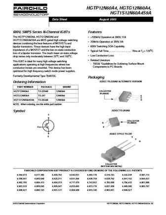
HGTP12N60A4, HGTG12N60A4, HGT1S12N60A4S9A Data Sheet August 2003 600V, SMPS Series N-Channel IGBTs Features The HGTP12N60A4, HGTG12N60A4 and >100kHz Operation at 390V, 12A HGT1S12N60A4S9A are MOS gated high voltage switching 200kHz Operation at 390V, 9A devices combining the best features of MOSFETs and 600V Switching SOA Capability bipolar transistors. These devices ha
ssr2n60a.pdf
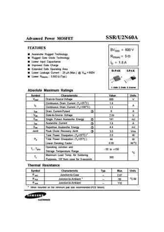
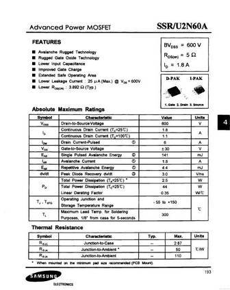
Advanced Power MOSFET FEATURES BVDSS = 600 V Avalanche Rugged Technology RDS(on) = 5 Rugged Gate Oxide Technology Lower Input Capacitance ID = 1.8 A Improved Gate Charge Extended Safe Operating Area Lower Leakage Current 25 A (Max.) @ VDS = 600V Lower RDS(ON) 3.892 (Typ.) 2 1 1 2 3 3 1. Gate 2. Drain 3. Source Absolute Maximum Ratings Symbol Charac
sss2n60a.pdf
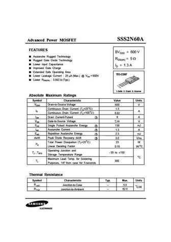
Advanced Power MOSFET FEATURES BVDSS = 600 V Avalanche Rugged Technology RDS(on) = 5 Rugged Gate Oxide Technology Lower Input Capacitance ID = 1.3 A Improved Gate Charge Extended Safe Operating Area Lower Leakage Current 25 A (Max.) @ VDS = 600V Lower RDS(ON) 3.892 (Typ.) 1 2 3 1.Gate 2. Drain 3. Source Absolute Maximum Ratings Symbol Characteristic Valu
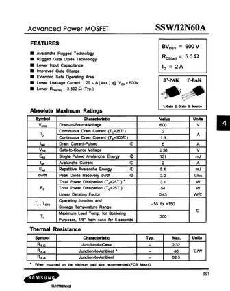
ssw2n60a.pdf
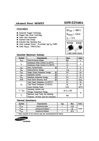
Advanced Power MOSFET FEATURES BVDSS = 600 V Avalanche Rugged Technology RDS(on) = 5.0 Rugged Gate Oxide Technology Lower Input Capacitance ID = 2 A Improved Gate Charge Extended Safe Operating Area Lower Leakage Current 25 A (Max.) @ VDS = 600V 2 Lower RDS(ON) 3.892 (Typ.) 1 1 2 3 3 1. Gate 2. Drain 3. Source Absolute Maximum Ratings Symbol Chara
ssp2n60a.pdf
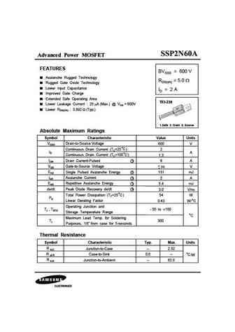
Advanced Power MOSFET FEATURES BVDSS = 600 V Avalanche Rugged Technology RDS(on) = 5.0 Rugged Gate Oxide Technology Lower Input Capacitance ID = 2 A Improved Gate Charge Extended Safe Operating Area Lower Leakage Current 25 A (Max.) @ VDS = 600V Lower RDS(ON) 3.892 (Typ.) 1 2 3 1.Gate 2. Drain 3. Source Absolute Maximum Ratings Symbol Characteristic Valu
siha22n60ael.pdf
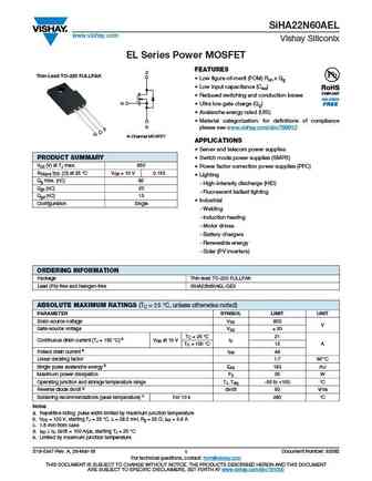
SiHA22N60AEL www.vishay.com Vishay Siliconix EL Series Power MOSFET FEATURES D Thin-Lead TO-220 FULLPAK Low figure-of-merit (FOM) Ron x Qg Low input capacitance (Ciss) Reduced switching and conduction losses G Ultra low gate charge (Qg) Avalanche energy rated (UIS) Material categorization for definitions of compliance S please see www.vishay.com/doc?999
siha22n60ae.pdf
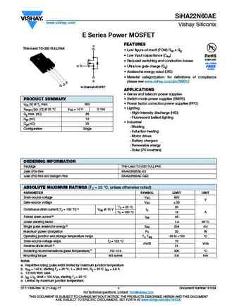
SiHA22N60AE www.vishay.com Vishay Siliconix E Series Power MOSFET FEATURES D Thin-Lead TO-220 FULLPAK Low figure-of-merit (FOM) Ron x Qg Low input capacitance (Ciss) Reduced switching and conduction losses G Ultra low gate charge (Qg) Available Avalanche energy rated (UIS) Material categorization for definitions of compliance S please see www.vishay.co
ixsn52n60au1.pdf
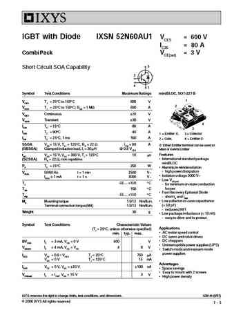
IGBT with Diode IXSN 52N60AU1 VCES = 600 V IC25 = 80 A Combi Pack VCE(sat) = 3 V 3 Short Circuit SOA Capability 2 4 1 Symbol Test Conditions Maximum Ratings miniBLOC, SOT-227 B 1 VCES TJ = 25 C to 150 C 600 V 2 VCGR TJ = 25 C to 150 C; RGE = 1 MW 600 A VGES Continuous 20 V VGEM Transient 30 V 4 IC25 TC = 25 C80 A 3 IC90 TC = 90 C40 A 1 = Emitter , 3 = Collector IC
ixgh72n60a3.pdf
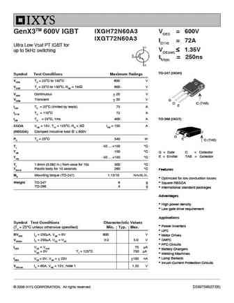
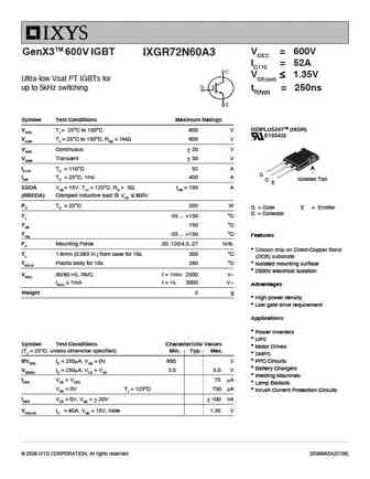
IXGH72N60A3 VCES = 600V GenX3TM 600V IGBT IXGT72N60A3 IC110 = 72A Ultra Low Vsat PT IGBT for VCE(sat) 1.35V up to 5kHz switching tfi(typ) = 250ns TO-247 (IXGH) Symbol Test Conditions Maximum Ratings VCES TC = 25 C to 150 C 600 V VCGR TJ = 25 C to 150 C, RGE = 1M 600 V VGES Continuous 20 V VGEM Transient 30 V G C C (TAB) E IC25 TC = 25 C (lim
ixgh32n60au1 ixgh32n60au1s.pdf
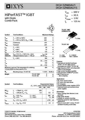
IXGH 32N60AU1 IXGH 32N60AU1S VCES = 600 V IC25 = 60 A HiPerFASTTM IGBT with Diode VCE(sat) = 2.9V Combi Pack tfi = 125 ns TO-247 SMD (32N60AU1S) Symbol Test Conditions Maximum Ratings VCES TJ = 25 C to 150 C 600 V G C (TAB) E VCGR TJ = 25 C to 150 C; RGE = 1 M 600 V VGES Continuous 20 V TO-247 AD VGEM Transient 30 V IC25 TC = 25 C60 A IC90 TC = 90 C32 A C (TAB)
ixgr72n60a3.pdf
VCES = 600V GenX3TM 600V IGBT IXGR72N60A3 IC110 = 52A VCE(sat) 1.35V Ultra-low Vsat PT IGBTs for up to 5kHz switching tfi(typ) = 250ns Symbol Test Conditions Maximum Ratings ISOPLUS247TM (IXGR) VCES TJ = 25 C to 150 C 600 V E153432 VCGR TJ = 25 C to 150 C, RGE = 1M 600 V VGES Continuous 20 V VGEM Transient 30 V IC110 TC = 110 C 52 A G ICM TC
ixgh32n60a.pdf

IXGH 32N60A IXGH 32N60AS VCES = 600 V IC25 = 60 A HiPerFASTTM IGBT VCE(sat) = 2.9 V tfi = 125 ns TO-247 SMD (32N60AS) Symbol Test Conditions Maximum Ratings C (TAB) VCES TJ = 25 C to 150 C 600 V G E VCGR TJ = 25 C to 150 C; RGE = 1 M 600 V VGES Continuous 20 V TO-247 AD VGEM Transient 30 V IC25 TC = 25 C60 A IC90 TC = 90 C32 A C (TAB) G ICM TC = 25 C, 1 ms 120
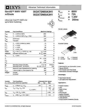
ixgr72n60a3h1.pdf
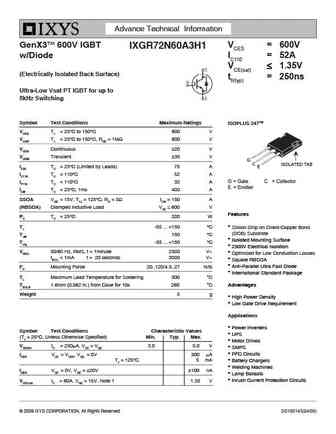
Advance Technical Information GenX3TM 600V IGBT VCES = 600V IXGR72N60A3H1 w/Diode IC110 = 52A VCE(sat) 1.35V (Electrically Isolated Back Surface) tfi(typ) = 250ns Ultra-Low Vsat PT IGBT for up to 5kHz Switching Symbol Test Conditions Maximum Ratings ISOPLUS 247TM VCES TJ = 25 C to 150 C 600 V VCGR TJ = 25 C to 150 C, RGE = 1M 600 V VGES Continuous
ixgt72n60a3.pdf

IXGH72N60A3 VCES = 600V GenX3TM 600V IGBT IXGT72N60A3 IC110 = 72A Ultra Low Vsat PT IGBT for VCE(sat) 1.35V up to 5kHz switching tfi(typ) = 250ns TO-247 (IXGH) Symbol Test Conditions Maximum Ratings VCES TC = 25 C to 150 C 600 V VCGR TJ = 25 C to 150 C, RGE = 1M 600 V VGES Continuous 20 V VGEM Transient 30 V G C C (TAB) E IC25 TC = 25 C (lim
ixgk72n60a3h1 ixgx72n60a3h1.pdf

Advance Technical Information GenX3TM 600V IGBT VCES = 600V IXGK72N60A3H1 w/Diode IC110 = 72A IXGX72N60A3H1 VCE(sat) 1.35V tfi(typ) = 250ns Ultra-Low Vsat PT IGBTs for up to 5kHz Switching TO-264 (IXGK) Symbol Test Conditions Maximum Ratings VCES TJ = 25 C to 150 C 600 V VCGR TJ = 25 C to 150 C, RGE = 1M 600 V (TAB) G VGES Continuous 20 V C E
ixgn72n60a3.pdf
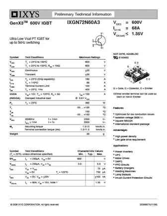
Preliminary Technical Information VCES = 600V IXGN72N60A3 GenX3TM 600V IGBT IC110 = 68A VCE(sat) 1.35V Ultra Low Vsat PT IGBT for up to 5kHz switching E SOT-227B, miniBLOC Symbol Test Conditions Maximum Ratings E153432 VCES TJ = 25 C to 150 C 600 V E VCGR TJ = 25 C to 150 C, RGE = 1M 600 V G VGES Continuous 20 V VGEM Transient 30 V IC25 TC
ixgk72n60a3h1.pdf
Advance Technical Information GenX3TM 600V IGBT VCES = 600V IXGK72N60A3H1 w/Diode IC110 = 72A IXGX72N60A3H1 VCE(sat) 1.35V tfi(typ) = 250ns Ultra-Low Vsat PT IGBTs for up to 5kHz Switching TO-264 (IXGK) Symbol Test Conditions Maximum Ratings VCES TJ = 25 C to 150 C 600 V VCGR TJ = 25 C to 150 C, RGE = 1M 600 V (TAB) G VGES Continuous 20 V C E
ixgx72n60a3h1.pdf

Advance Technical Information GenX3TM 600V IGBT VCES = 600V IXGK72N60A3H1 w/Diode IC110 = 72A IXGX72N60A3H1 VCE(sat) 1.35V tfi(typ) = 250ns Ultra-Low Vsat PT IGBTs for up to 5kHz Switching TO-264 (IXGK) Symbol Test Conditions Maximum Ratings VCES TJ = 25 C to 150 C 600 V VCGR TJ = 25 C to 150 C, RGE = 1M 600 V (TAB) G VGES Continuous 20 V C E
ixsa12n60au1.pdf
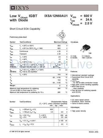
IXSA 12N60AU1 VCES = 600 V Low VCE(sat) IGBT IC25 = 24 A with Diode VCE(sat) = 2.5 V Short Circuit SOA Capability Preliminary data sheet Symbol Test Conditions Maximum Ratings TO-263AA VCES TJ = 25 C to 150 C 600 V VCGR TJ = 25 C to 150 C; RGE = 1 M 600 V G VGES Continuous 20 V E TAB VGEM Transient 30 V G = Gate, C = Collector, IC25 TC = 25 C24 A E = Emitter
ixgh32n60as.pdf
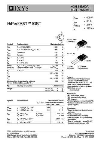
IXGH 32N60A IXGH 32N60AS VCES = 600 V IC25 = 60 A HiPerFASTTM IGBT VCE(sat) = 2.9 V tfi = 125 ns TO-247 SMD (32N60AS) Symbol Test Conditions Maximum Ratings C (TAB) VCES TJ = 25 C to 150 C 600 V G E VCGR TJ = 25 C to 150 C; RGE = 1 M 600 V VGES Continuous 20 V TO-247 AD VGEM Transient 30 V IC25 TC = 25 C60 A IC90 TC = 90 C32 A C (TAB) G ICM TC = 25 C, 1 ms 120
hgtg12n60a4d hgtp12n60a4d hgt1s12n60a4ds.pdf
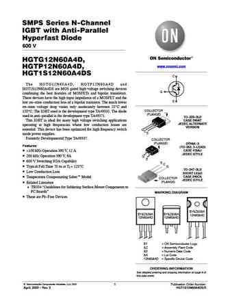
SMPS Series N-Channel IGBT with Anti-Parallel Hyperfast Diode 600 V HGTG12N60A4D, www.onsemi.com HGTP12N60A4D, HGT1S12N60A4DS C The HGTG12N60A4D, HGTP12N60A4D and HGT1S12N60A4DS are MOS gated high voltage switching devices G combining the best features of MOSFETs and bipolar transistors. These devices have the high input impedance of a MOSFET and the E low on-state conduction los
aou2n60a.pdf
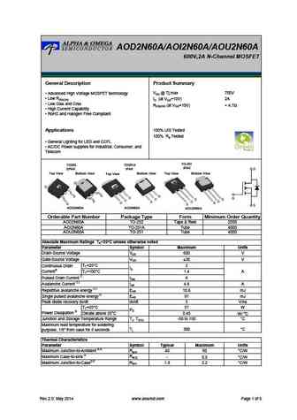
AOD2N60A/AOI2N60A/AOU2N60A 600V,2A N-Channel MOSFET General Description Product Summary VDS @ Tj,max 700V Advanced High Voltage MOSFET technology Low RDS(ON) ID (at VGS=10V) 2A Low Ciss and Crss RDS(ON) (at VGS=10V)
aoi2n60a.pdf

AOD2N60A/AOI2N60A/AOU2N60A 600V,2A N-Channel MOSFET General Description Product Summary VDS @ Tj,max 700V Advanced High Voltage MOSFET technology Low RDS(ON) ID (at VGS=10V) 2A Low Ciss and Crss RDS(ON) (at VGS=10V)
aod2n60a.pdf

AOD2N60A/AOI2N60A/AOU2N60A 600V,2A N-Channel MOSFET General Description Product Summary VDS @ Tj,max 700V Advanced High Voltage MOSFET technology Low RDS(ON) ID (at VGS=10V) 2A Low Ciss and Crss RDS(ON) (at VGS=10V)
12n60a 12n60af.pdf
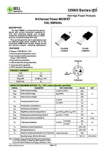
RoHS I2N60 Series RoHS SEMICONDUCTOR Nell High Power Products N-Channel Power MOSFET 12A, 600Volts DESCRIPTION The Nell 12N60 is a three-terminal silicon device with current conduction capability of D 12A, fast switching speed, low on-state resistance, breakdown voltage rating of 600V, and max. threshold voltage of 4 volts. They are designed for use in applications such as s
cm12n60a to220a.pdf
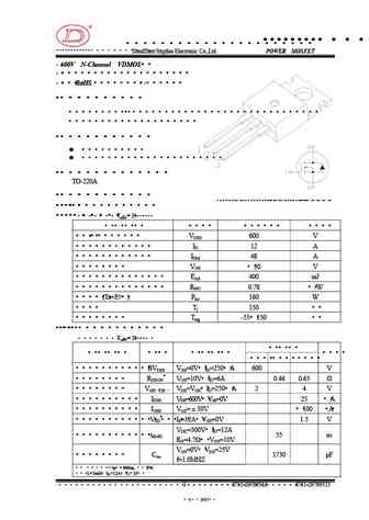
R CM12N60A www.jdsemi.cn ShenZhen Jingdao Electronic Co.,Ltd. POWER MOSFET 600V N-Channel VDMOS RoHS 1 LD E 2 3
cm12n60af.pdf
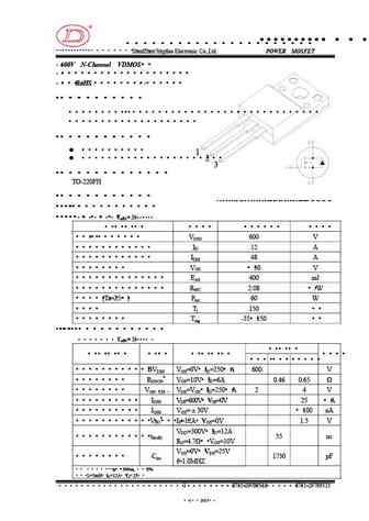
R CM12N60AF www.jdsemi.cn ShenZhen Jingdao Electronic Co.,Ltd. POWER MOSFET 600V N-Channel VDMOS RoHS 1 LD E 2 1
bl12n60a-p bl12n60a-a.pdf
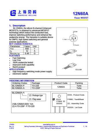
12N60A Power MOSFET 1 Description Step-Down Converter BL12N60A, the silicon N-channel Enhanced , MOSFETs, is obtained by advanced MOSFET technology which reduce the conduction loss, improve switching performance and enhance the avalanche energy. The transistor is suitable device for SMPS, high speed switching and general purpose applications. KEY CHARACTERISTICS Par
fhf2n60a fhp2n60a fhu2n60a fhd2n60a.pdf
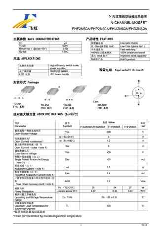
N N-CHANNEL MOSFET FHF2N60A/FHP2N60A/FHU2N60A/FHD2N60A MAIN CHARACTERISTICS FEATURES ID 2A Low gate charge VDSS 600V Crss ( 6pF) Low Crss (typical 6pF ) Rdson-typ @Vgs=10V 3.5 Fast switching Qg-typ 8.0nC 100% 100% avalanche tested dv/
fhp12n60a fhf12n60a.pdf
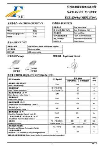
N N-CHANNEL MOSFET FHP12N60A/ FHF12N60A MAIN CHARACTERISTICS FEATURES Low gate charge ID 12A Crss ( 18pF) Low Crss (typical 18pF ) VDSS 600V Fast switching Rdson-typ 0.6 @Vgs=10V 100% 100% avalanche tested Qg-typ 52nC dv/dt Im
sw2n60a1.pdf
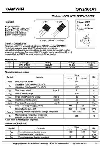
SAMWIN SW2N60A1 SW2N60A1 N-channel IPAK/TO-220F MOSFET TO-251 TO-220F BVDSS 600V Features ID 2.0A High ruggedness RDS(ON) 5.0ohm RDS(ON) (Max 5.0 )@VGS=10V Gate Charge (Typical 10nC) Improved dv/dt Capability 1 1 2 100% Avalanche Tested 2 2 3 3 1. Gate 2. Drain 3. Source 1 General Description 3 This power MOSFET is produced w
tmp12n60a tmpf12n60a.pdf
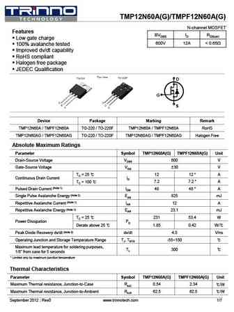
TMP12N60A(G)/TMPF12N60A(G) N-channel MOSFET Features BVDSS ID RDS(on) Low gate charge 600V 12A
tmp2n60az tmpf2n60az.pdf
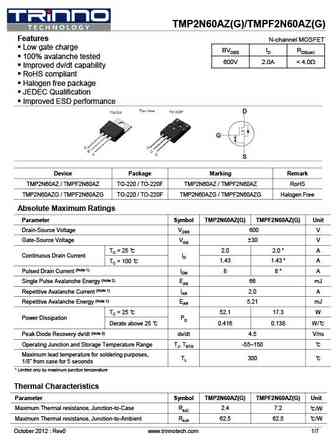
TMP2N60AZ(G)/TMPF2N60AZ(G) Features N-channel MOSFET Low gate charge BVDSS ID RDS(on) 100% avalanche tested 600V 2.0A
tmd2n60az tmu2n60az.pdf
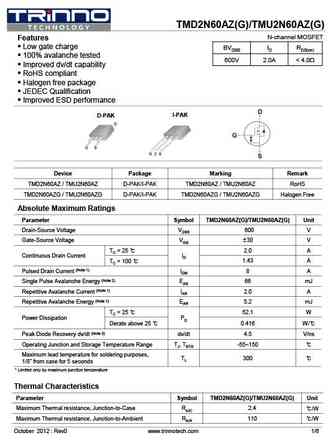
TMD2N60AZ(G)/TMU2N60AZ(G) N-channel MOSFET Features Low gate charge BVDSS ID RDS(on) 100% avalanche tested 600V 2.0A
cs12n60a8hd.pdf
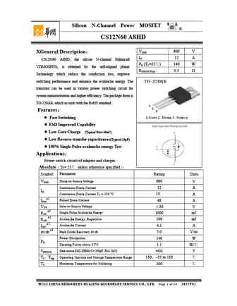
Silicon N-Channel Power MOSFET R CS12N60 A8HD VDSS 600 V XGeneral Description ID 12 A CS12N60 A8HD, the silicon N-channel Enhanced PD (TC=25 ) 140 W VDMOSFETs, is obtained by the self-aligned planar RDS(ON)Typ 0.5 Technology which reduce the conduction loss, improve switching performance and enhance the avalanche energy. The transistor can be used in various
cs2n60a7h.pdf
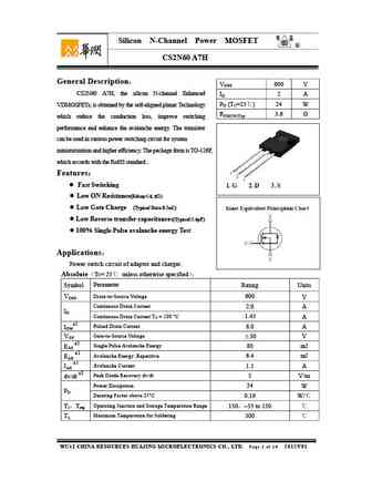
Silicon N-Channel Power MOSFET R CS2N60 A7H General Description VDSS 600 V CS2N60 A7H, the silicon N-channel Enhanced ID 2 A PD (TC=25 ) 24 W VDMOSFETs, is obtained by the self-aligned planar Technology RDS(ON)Typ 3.6 which reduce the conduction loss, improve switching performance and enhance the avalanche energy. The transistor can be used in various power
cs2n60a3h.pdf
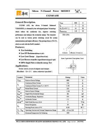
Silicon N-Channel Power MOSFET R CS2N60 A3H General Description VDSS 600 V CS2N60 A3H, the silicon N-channel Enhanced ID 2 A PD (TC=25 ) 35 W VDMOSFETs, is obtained by the self-aligned planar Technology RDS(ON)Typ 3.6 which reduce the conduction loss, improve switching performance and enhance the avalanche energy. The transistor can be used in various power
cs2n60a4t.pdf
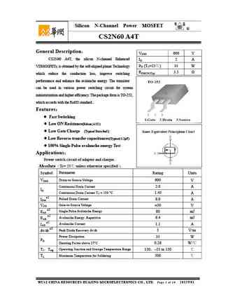
Silicon N-Channel Power MOSFET R CS2N60 A4T General Description VDSS 600 V CS2N60 A4T, the silicon N-channel Enhanced ID 2 A PD (TC=25 ) 35 W VDMOSFETs, is obtained by the self-aligned planar Technology RDS(ON)Typ 3.5 which reduce the conduction loss, improve switching performance and enhance the avalanche energy. The transistor can be used in various power
cs2n60a4h.pdf
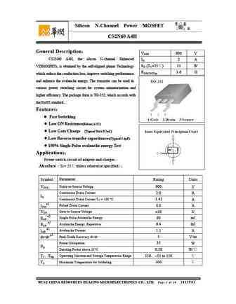
Silicon N-Channel Power MOSFET R CS2N60 A4H General Description VDSS 600 V CS2N60 A4H, the silicon N-channel Enhanced ID 2 A PD (TC=25 ) 35 W VDMOSFETs, is obtained by the self-aligned planar Technology RDS(ON)Typ 3.6 which reduce the conduction loss, improve switching performance and enhance the avalanche energy. The transistor can be used in various power
cs12n60a8h.pdf
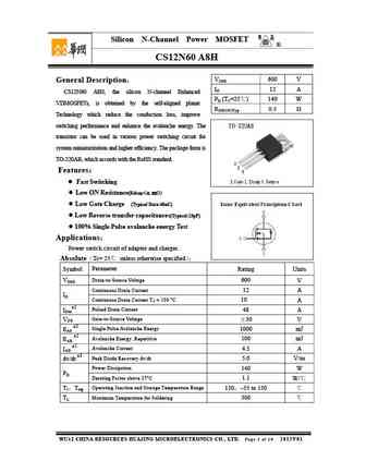
Silicon N-Channel Power MOSFET R CS12N60 A8H VDSS 600 V General Description ID 12 A CS12N60 A8H, the silicon N-channel Enhanced PD (TC=25 ) 140 W VDMOSFETs, is obtained by the self-aligned planar RDS(ON)Typ 0.5 Technology which reduce the conduction loss, improve switching performance and enhance the avalanche energy. The transistor can be used in various po
fir2n60alg.pdf

FIR2N60ALG Advanced N-Ch Power MOSFET PIN Connection TO-252(D-PAK) General Description FIR2N60ALG is an N-channel enhancement mode power MOS field effect transistor which is produced using Silan D proprietary F-CellTM structure VDMOS technology. The improved G planar stripe cell and the improved guard ring terminal have been especially tailored to minimize on-state resistance, prov
fir2n60afg.pdf
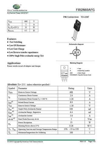
FIR2N60AFG N-Channel Power MOSFET PIN Connection TO-220F VDSS 600 V ID 2 A PD (TC=25 ) 35 W RDS(ON) 4.5 G Features D S Fast Switching g Schematic dia ram Low ON Resistance D Low Gate Charge Low Reverse transfer capacitances G 100% Single Pulse avalanche energy Test S Marking Diagram Applications Power switch circuit of adaptor and charger. Y = Year
aou2n60a.pdf

isc N-Channel MOSFET Transistor AOU2N60A FEATURES Drain Current I = 2A@ T =25 D C Drain Source Voltage- V =600V(Min) DSS Static Drain-Source On-Resistance R =4.7 (Max) DS(on) 100% avalanche tested Minimum Lot-to-Lot variations for robust device performance and reliable operation DESCRIPTION Designed for use in switch mode power supplies and general purpose
aoi2n60a.pdf
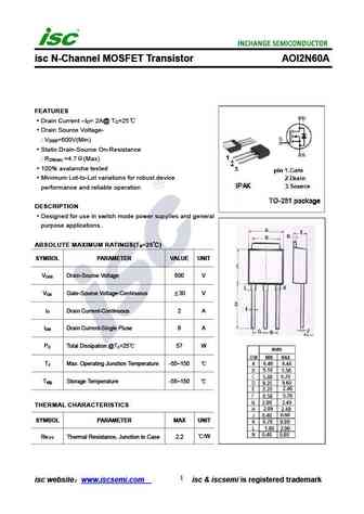
isc N-Channel MOSFET Transistor AOI2N60A FEATURES Drain Current I = 2A@ T =25 D C Drain Source Voltage- V =600V(Min) DSS Static Drain-Source On-Resistance R =4.7 (Max) DS(on) 100% avalanche tested Minimum Lot-to-Lot variations for robust device performance and reliable operation DESCRIPTION Designed for use in switch mode power supplies and general purpose
aod2n60a.pdf
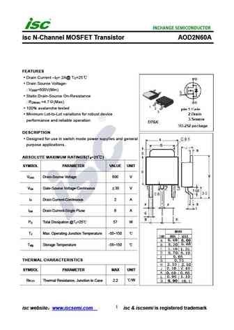
isc N-Channel MOSFET Transistor AOD2N60A FEATURES Drain Current I = 2A@ T =25 D C Drain Source Voltage- V =600V(Min) DSS Static Drain-Source On-Resistance R =4.7 (Max) DS(on) 100% avalanche tested Minimum Lot-to-Lot variations for robust device performance and reliable operation DESCRIPTION Designed for use in switch mode power supplies and general purpose
Otros transistores... 2N6092 , 2N6093 , 2N6094 , 2N6095 , 2N6096 , 2N6097 , 2N6098 , 2N6099 , A42 , 2N60B , 2N60C , 2N61 , 2N610 , 2N6100 , 2N6101 , 2N6102 , 2N6103 .


Liste
Recientemente añadidas las descripciónes de los transistores:
BJT: GA1A4M | SBT42 | 2SA200-Y | 2SA200-O | 2SD882-Q | 2SD882-P | 2SD882-E | 2SC945-L | 2SC945-H | 2SC4226-R23 | 2SC3357-F | 2SC3357-E | 2SC3356-R26 | 2SC3356-R24 | 2SC3356-R23 | 2SB772-Q | 2SB772-P | 2SB772-E | 2SA1015-L | 2SA1015-H | HSS8550
Popular searches
a933 transistor datasheet | a1633 transistor | 2sa844 | 2sc1327 | 2sc3855 | 2sc945 transistor equivalent | 2sd427 | mje15032 equivalent