MMBT7002KW Specs and Replacement
Type Designator: MMBT7002KW
Type of Transistor: MOSFET
Type of Control Channel: N-Channel
Absolute Maximum Ratings
Pd ⓘ - Maximum Power Dissipation: 0.2 W
|Vds|ⓘ - Maximum Drain-Source Voltage: 60 V
|Vgs|ⓘ - Maximum Gate-Source Voltage: 20 V
|Id| ⓘ - Maximum Drain Current: 0.3 A
Tj ⓘ - Maximum Junction Temperature: 150 °C
Electrical Characteristics
Cossⓘ - Output Capacitance: 25 pF
RDSonⓘ - Maximum Drain-Source On-State Resistance: 3 Ohm
Package: SOT323
MMBT7002KW substitution
- MOSFET ⓘ Cross-Reference Search
MMBT7002KW datasheet
mmbt7002kw.pdf
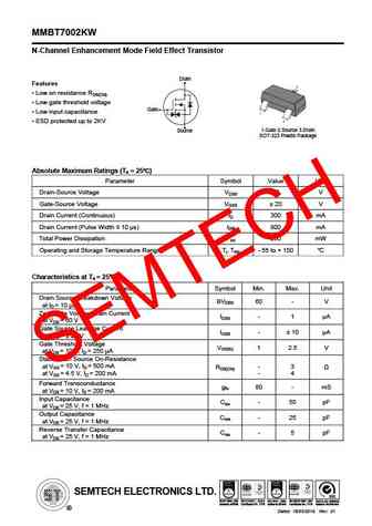
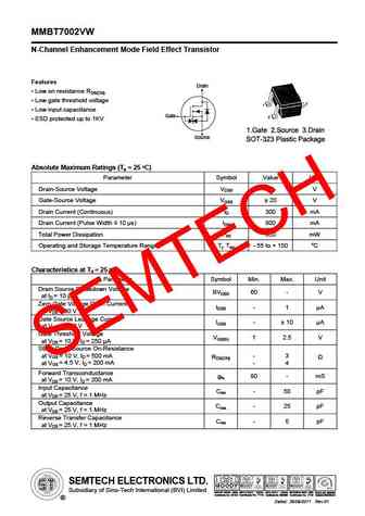
MMBT7002KW N-Channel Enhancement Mode Field Effect Transistor Drain Features Low on resistance RDS(ON) Low gate threshold voltage Gate Low input capacitance ESD protected up to 2KV 1.Gate 2.Source 3.Drain Source SOT-323 Plastic Package Absolute Maximum Ratings (Ta = 25 ) Parameter Symbol Value Unit Drain-Source Voltage VDSS 60 V Gate-Source Voltage VGSS ... See More ⇒
mmbt7002k.pdf
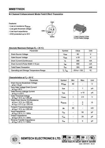
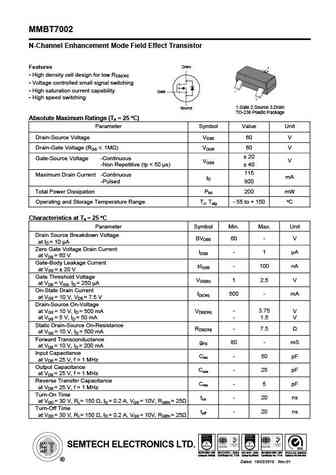
MMBT7002K N-Channel Enhancement Mode Field Effect Transistor Drain Features Low on resistance RDS(ON) Low gate threshold voltage Gate Low input capacitance ESD protected up to 2KV 1.Gate 2.Source 3.Drain Source TO-236 Plastic Package O Absolute Maximum Ratings (Ta = 25 C) Parameter Symbol Value Unit Drain-Source Voltage VDSS 60 V Gate-Source Voltage VGSS ... See More ⇒
mmbt7002e.pdf
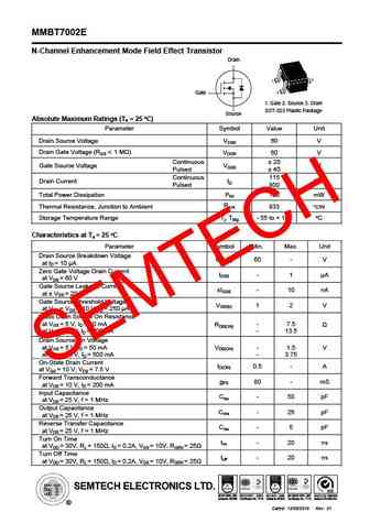
MMBT7002E N-Channel Enhancement Mode Field Effect Transistor Drain Gate 1. Gate 2. Source 3. Drain SOT-523 Plastic Package Source O Absolute Maximum Ratings (Ta = 25 C) Parameter Symbol Value Unit Drain Source Voltage VDSS 60 V Drain Gate Voltage (RGS 1 M ) VDGR 60 V Continuous 20 V Gate Source Voltage VGSS Pulsed 40 Continuous 115 mA Drain Current ID ... See More ⇒
mmbt7002w.pdf
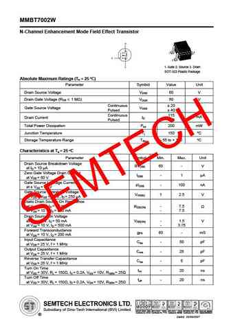
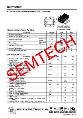
MMBT7002W N-Channel Enhancement Mode Field Effect Transistor 1. Gate 2. Source 3. Drain SOT-323 Plastic Package O Absolute Maximum Ratings (Ta = 25 C) Parameter Symbol Value Unit Drain Source Voltage VDSS 60 V Drain Gate Voltage (RGS 1 M ) VDGR 60 V Continuous 20 V Gate Source Voltage VGSS Pulsed 40 Continuous 115 mA Drain Current ID Pulsed 800 Total Powe... See More ⇒
Detailed specifications: SSPL4004, SSPL50N30H, SSPL5505, SSPL5508, MMBT7002, MMBT7002DW, MMBT7002E, MMBT7002K, EMB04N03H, MMBT7002VW, MMBT7002W, MMFTN123, MMFTN138, MMFTN170, MMFTN20, MMFTN2302, MMFTN2306
Keywords - MMBT7002KW MOSFET specs
MMBT7002KW cross reference
MMBT7002KW equivalent finder
MMBT7002KW pdf lookup
MMBT7002KW substitution
MMBT7002KW replacement
Step-by-step guide to finding a MOSFET replacement. Cross-reference parts and ensure compatibility for your repair or project.
🌐 : EN ES РУ
LIST
Last Update
MOSFET: AUB034N10 | AUB033N08BG | AUB026N085 | AUA062N08BG | AUA060N08AG | AUA056N08BGL | AUA039N10 | ASW80R290E | ASW65R120EFD | ASW65R110E
Popular searches
m3056m mosfet | skd502t mosfet | tip 35 transistor | bu2508df | 2n2222a transistor equivalent | 2sc2509 | 2n1815 | 2sa1103
