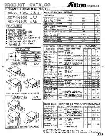
4N100L-TA3-T Specs and Replacement
Type Designator: 4N100L-TA3-T
Type of Transistor: MOSFET
Type of Control Channel: N-Channel
Absolute Maximum Ratings
Pd ⓘ
- Maximum Power Dissipation: 140 W
|Vds|ⓘ - Maximum Drain-Source Voltage: 1000 V
|Vgs|ⓘ - Maximum Gate-Source Voltage: 30 V
|Id| ⓘ - Maximum Drain Current: 4 A
Tj ⓘ - Maximum Junction Temperature: 150 °C
Electrical Characteristics
tr ⓘ - Rise Time: 115 nS
Cossⓘ -
Output Capacitance: 90 pF
RDSonⓘ - Maximum Drain-Source On-State Resistance: 3.5 Ohm
Package: TO220
4N100L-TA3-T substitution
- MOSFET ⓘ Cross-Reference Search
4N100L-TA3-T datasheet
8.1. Size:111K ixys
ixth4n100l.pdf 
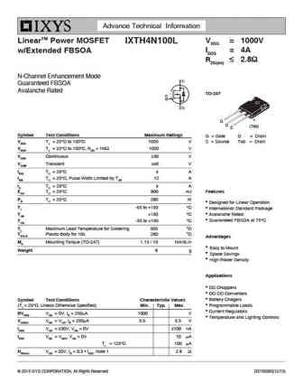
Advance Technical Information LinearTM Power MOSFET VDSS = 1000V IXTH4N100L ID25 = 4A w/Extended FBSOA RDS(on) 2.8 N-Channel Enhancement Mode Guaranteed FBSOA Avalanche Rated TO-247 G D (Tab) S Symbol Test Conditions Maximum Ratings G = Gate D = Drain VDSS TJ = 25 C to 150 C 1000 V S = Source Tab = Drain VDGR TJ = 25 C to 150 ... See More ⇒
9.1. Size:51K 1
hgtg34n100e2.pdf 
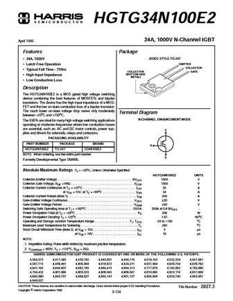
S E M I C O N D U C T O R HGTG34N100E2 34A, 1000V N-Channel IGBT April 1995 Features Package JEDEC STYLE TO-247 34A, 1000V EMITTER Latch Free Operation COLLECTOR Typical Fall Time - 710ns COLLECTOR GATE (BOTTOM SIDE High Input Impedance METAL) Low Conduction Loss Description The HGTG34N100E2 is a MOS gated high voltage switching device combining the best fea... See More ⇒
9.2. Size:199K motorola
mty14n100e.pdf 
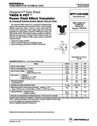
MOTOROLA Order this document SEMICONDUCTOR TECHNICAL DATA by MTY14N100E/D Designer's Data Sheet MTY14N100E TMOS E-FET. Motorola Preferred Device Power Field Effect Transistor N Channel Enhancement Mode Silicon Gate TMOS POWER FET This advanced TMOS power FET is designed to withstand high 14 AMPERES energy in the avalanche and commutation modes. This new energy 1000 VOLTS... See More ⇒
9.3. Size:232K motorola
mgy14n100e.pdf 
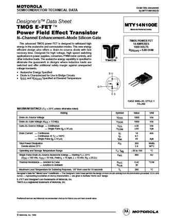
MOTOROLA Order this document SEMICONDUCTOR TECHNICAL DATA by MTY14N100E/D Designer's Data Sheet MTY14N100E TMOS E-FET. Motorola Preferred Device Power Field Effect Transistor N Channel Enhancement Mode Silicon Gate TMOS POWER FET This advanced TMOS power FET is designed to withstand high 14 AMPERES energy in the avalanche and commutation modes. This new energy 1000 VOLTS... See More ⇒
9.4. Size:366K st
stp4n100.pdf 
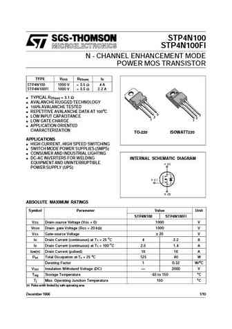
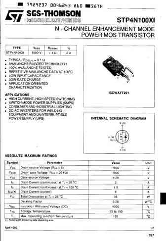
STP4N100 STP4N100FI N - CHANNEL ENHANCEMENT MODE POWER MOS TRANSISTOR TYPE VDSS RDS(on) ID STP4N100 1000 V ... See More ⇒
9.6. Size:93K fairchild semi
rfp4n100 rf1s4n100sm.pdf 
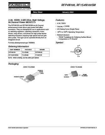
RFP4N100, RF1S4N100SM Data Sheet January 2002 4.3A, 1000V, 3.500 Ohm, High Voltage, Features N-Channel Power MOSFETs 4.3A, 1000V The RFP4N100 and RFP4N100SM are N-Channel rDS(ON) = 3.500 enhancement mode silicon gate power field effect UIS Rating Curve (Single Pulse) transistors. They are designed for use in applications such as switching regulators, switching conver... See More ⇒
9.8. Size:124K ixys
ixfk24n100q3 ixfx24n100q3.pdf 
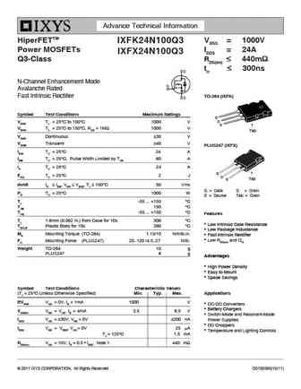
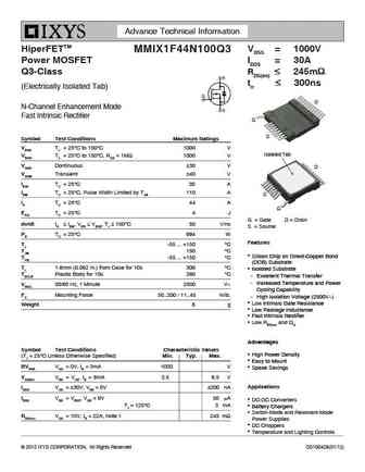
Advance Technical Information HiperFETTM VDSS = 1000V IXFK24N100Q3 Power MOSFETs ID25 = 24A IXFX24N100Q3 Q3-Class RDS(on) 440m trr 300ns N-Channel Enhancement Mode Avalanche Rated Fast Intrinsic Rectifier TO-264 (IXFK) Symbol Test Conditions Maximum Ratings G VDSS TJ = 25 C to 150 C 1000 V D S VDGR TJ = 25 C to 150 ... See More ⇒
9.9. Size:112K ixys
ixfr24n100.pdf 
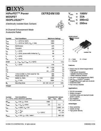
HiPerFETTM Power VDSS = 1000V IXFR24N100 ID25 = 22A MOSFET RDS(on) 390m ISOPLUS247TM t 250ns (Electrically Isolated Back Surface) rr N-Channel Enhancement Mode Avalanche Rated ISOPLUS247 E153432 Symbol Test Conditions Maximum Ratings VDSS TJ = 25 C to 150 C 1000 V VDGR TJ = 25 C to 150 C, RGS = 1M 1000 V VGSS Co... See More ⇒
9.10. Size:108K ixys
ixfn24n100.pdf 
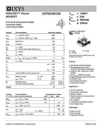
HiPerFETTM Power VDSS = 1000V IXFN24N100 MOSFET ID25 = 24A RDS(on) 390m N-Channel Enhancement Mode trr 250ns Avalanche Rated Fast Intrinsic Diode miniBLOC, SOT-227 B Symbol Test Conditions Maximum Ratings E153432 VDSS TJ = 25 C to 150 C 1000 V S G VDGR TJ = 25 C to 150 C, RGS = 1M 1000 V VGSS Continuous 20 V V... See More ⇒
9.11. Size:116K ixys
ixfl34n100.pdf 
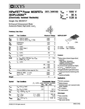
IXFL 34N100 VDSS = 1000 V IXFL 34N100 VDSS = 1000 V IXFL 34N100 VDSS = 1000 V IXFL 34N100 VDSS = 1000 V IXFL 34N100 VDSS = 1000 V HiPerFETTM Power MOSFETs HiPerFETTM Power MOSFETs HiPerFETTM Power MOSFETs HiPerFETTM Power MOSFETs HiPerFETTM Power MOSFETs ID25 = 30 A ID25 = 30 A ISOPLUS264TM ID25 = 30 A ISOPLUS264TM ID25 = 30 A ISOPLUS264TM ID25 = 30 A ISOPLUS264TM ISOPLUS264TM ... See More ⇒
9.12. Size:141K ixys
ixfr24n100q3.pdf 
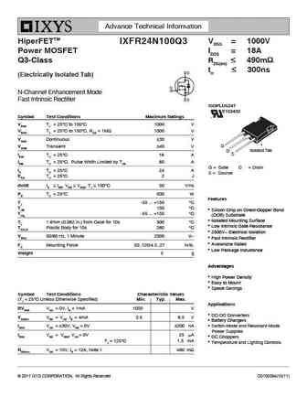
Advance Technical Information HiperFETTM VDSS = 1000V IXFR24N100Q3 Power MOSFET ID25 = 18A Q3-Class RDS(on) 490m trr 300ns (Electrically Isolated Tab) N-Channel Enhancement Mode Fast Intrinsic Rectifier ISOPLUS247 E153432 Symbol Test Conditions Maximum Ratings VDSS TJ = 25 C to 150 C 1000 V VDGR TJ = 25 C to 150 C, R... See More ⇒
9.14. Size:133K ixys
ixfk24n100 ixfx24n100.pdf 
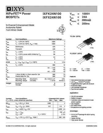
VDSS = 1000V HiPerFETTM Power IXFK24N100 ID25 = 24A MOSFETs IXFX24N100 RDS(on) 390m t 250ns rr N-Channel Enhancement Mode Avalanche Rated Fast Intrisic Diode TO-264 (IXFK) Symbol Test Conditions Maximum Ratings VDSS TJ = 25 C to 150 C 1000 V VDGR TJ = 25 C to 150 C, RGS = 1M 1000 V VGSS Continuous 20 V G (T... See More ⇒
9.16. Size:103K ixys
ixga4n100.pdf 
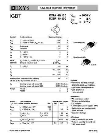
Advanced Technical Information IXGA 4N100 VCES = 1000 V IGBT IXGP 4N100 IC25 = 8 A VCE(sat) = 2.7 V Symbol Test Conditions Maximum Ratings VCES TJ = 25 C to 150 C 1000 V TO-220AB (IXGP) VCGR TJ = 25 C to 150 C; RGE = 1 MW 1000 V VGES Continuous 20 V VGEM Transient 30 V G C E IC25 TC = 25 C8 A IC90 TC = 90 C4 A ICM TC = 25 C, 1 ms 16 A TO-263 AA (IXGA) SSOA VGE = 1... See More ⇒
9.17. Size:79K ixys
ixfr4n100q.pdf 
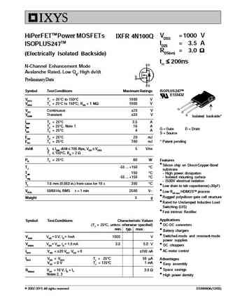
HiPerFETTM Power MOSFETs VDSS =1000 V IXFR 4N100Q ID25 = 3.5 A ISOPLUS247TM RDS(on) = 3.0 (Electrically Isolated Backside) trr 200ns N-Channel Enhancement Mode Avalanche Rated, Low Qg, High dv/dt Preliminary Data Symbol Test Conditions Maximum Ratings ISOPLUS 247TM E153432 VDSS TJ = 25 C to 150 C 1000 V VDGR TJ = 25 C to 150 C;... See More ⇒
9.18. Size:116K ixys
ixfh14n100 ixft14n100 ixfx14n100 ixfh15n100 ixft15n100 ixfx15n100.pdf 
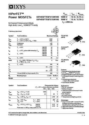
VDSS ID25 RDS(on) HiPerFETTM IXFH/IXFT/IXFX14 N100 1000 V 14 A 0.75 W Power MOSFETs IXFH/IXFT/IXFX15 N100 1000 V 15 A 0.70 W trr 200 ns N-Channel Enhancement Mode High dv/dt, Low trr, HDMOSTM Family Preliminary data sheet TO-247 AD Symbol Test Conditions Maximum Ratings (IXFH) VDSS TJ = 25 C to 150 C 1000 V VDGR TJ = 25 C to 150 C; RGS = 1 MW 1000 V (TAB) VGS Continuous ... See More ⇒
9.19. Size:45K ixys
ixth14n100.pdf 
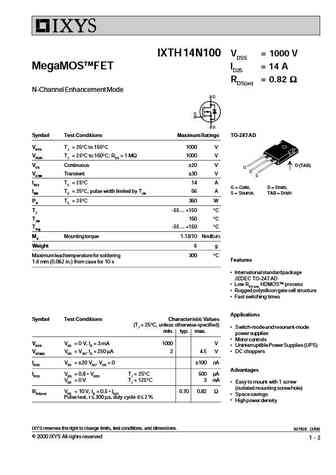
IXTH 14N100 VDSS = 1000 V MegaMOSTMFET ID25 = 14 A RDS(on) = 0.82 N-Channel Enhancement Mode Symbol Test Conditions Maximum Ratings TO-247 AD VDSS TJ = 25 C to 150 C 1000 V VDGR TJ = 25 C to 150 C; RGS = 1 M 1000 V VGS Continuous 20 V D (TAB) VGSM Transient 30 V ID25 TC = 25 C14 A G = Gate, D = Drain, IDM TC = 25 C, pulse width limited by TJM 56 A... See More ⇒
9.20. Size:103K ixys
ixgp4n100.pdf 
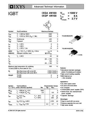
Advanced Technical Information IXGA 4N100 VCES = 1000 V IGBT IXGP 4N100 IC25 = 8 A VCE(sat) = 2.7 V Symbol Test Conditions Maximum Ratings VCES TJ = 25 C to 150 C 1000 V TO-220AB (IXGP) VCGR TJ = 25 C to 150 C; RGE = 1 MW 1000 V VGES Continuous 20 V VGEM Transient 30 V G C E IC25 TC = 25 C8 A IC90 TC = 90 C4 A ICM TC = 25 C, 1 ms 16 A TO-263 AA (IXGA) SSOA VGE = 1... See More ⇒
9.21. Size:142K ixys
ixfa4n100q-trl.pdf 
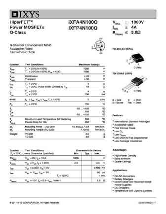
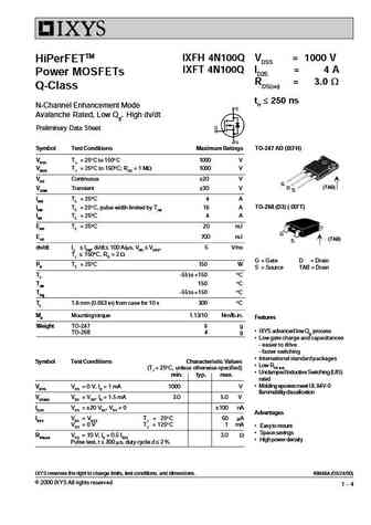
HiperFETTM VDSS = 1000V IXFA4N100Q Power MOSFETs ID25 = 4A IXFP4N100Q Q-Class RDS(on) 3.0 N-Channel Enhancement Mode Avalanche Rated TO-263 AA (IXFA) Fast Intrinsic Diode G S Symbol Test Conditions Maximum Ratings D (Tab) VDSS TJ = 25 C to 150 C 1000 V VDGR TJ = 25 C to 150 C, RGS = 1M 1000 V TO-220AB (IXFP) VGSS Continuous 20 V VGS... See More ⇒
9.22. Size:570K ixys
ixfn34n100.pdf 
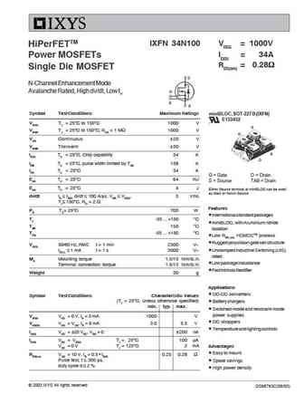
IXFN 34N100 VDSS = 1000V HiPerFETTM ID25 = 34A Power MOSFETs RDS(on) = 0.28 Single Die MOSFET D N-Channel Enhancement Mode Avalanche Rated, High dv/dt, Low trr G S S Symbol Test Conditions Maximum Ratings miniBLOC, SOT-227 B (IXFN) E153432 VDSS TJ = 25 C to 150 C 1000 V S VDGR TJ = 25 C to 150 C; RGS = 1 M 1000 V G VGS Continuous 20 V VGSM Tran... See More ⇒
9.24. Size:799K pipsemi
pta04n100.pdf 
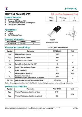
PTA04N100 1000V N-ch Planar MOSFET General Features BVDSS RDS(ON),typ. ID RoHS Compliant 1000V 2.0 4.0A RDS(ON),typ.=2.0 @VGS=10V Low Gate Charge Minimize Switching Loss Fast Recovery Body Diode Applications Adaptor Charger G SMPS Standby Power D S Ordering Information TO-220F Part Number Package Brand Package No to Scale PT... See More ⇒
9.25. Size:707K samwin
swf4n100u.pdf 
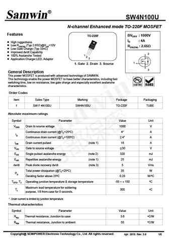
SW4N100U N-channel Enhanced mode TO-220F MOSFET Features BVDSS 1000V TO-220F ID 4A High ruggedness Low RDS(ON) (Typ 2.65 )@VGS=10V RDS(ON) 2.65 Low Gate Charge (Typ 33nC) Improved dv/dt Capability 2 1 100% Avalanche Tested 2 3 Application Charger,LED, Adaptor 1 1. Gate 2. Drain 3. Source 3 General Description This pow... See More ⇒
9.26. Size:1105K way-on
wml4n100d1.pdf 
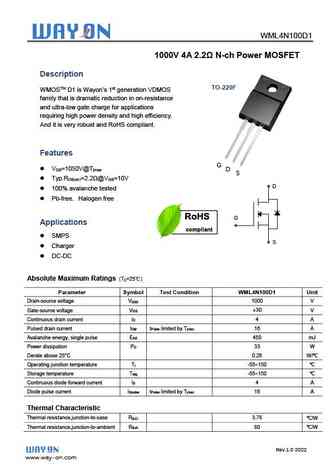
WML4N100D1 1000V 4A 2.2 N-ch Power MOSFET Description TO-220F WMOSTM D1 is Wayon s 1st generation VDMOS family that is dramatic reduction in on-resistance and ultra-low gate charge for applications requiring high power density and high efficiency. And it is very robust and RoHS compliant. Features G V =1050V@T DS jmax D S Typ.R =2.2 @V =10V DS(on) G... See More ⇒
9.27. Size:525K convert
cs4n100f cs4n100v cs4n100vf.pdf 
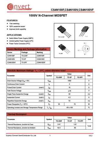
nvert Suzhou Convert Semiconductor Co ., Ltd. CS4N100F,CS4N100V,CS4N100VF 1000V N-Channel MOSFET FEATURES Fast switching 100% avalanche tested Improved dv/dt capability APPLICATIONS Switch Mode Power Supply (SMPS) Uninterruptible Power Supply (UPS) Power Factor Correction (PFC) Device Marking and Package Information Device Package Marking CS4N100F TO-220F C... See More ⇒
9.28. Size:860K cn scilicon
sfg014n100bc3.pdf 
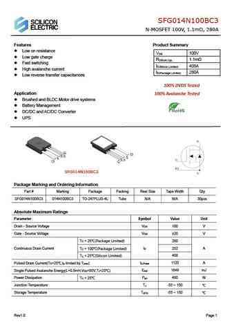
SFG014N100BC3 N-MOSFET 100V, 1.1m , 280A Features Product Summary Low on resistance V 100V DS Low gate charge R 1.1m DS(on) typ. Fast switching I 408A D(Silicon Limited) High avalanche current I 280A D(Package Limited) Low reverse transfer capacitances 100% DVDS Tested Application 100% Avalanche Tested Brushed and BLDC Motor drive systems ... See More ⇒
9.29. Size:643K cn scilicon
sfp046n100c3 sfb044n100c3.pdf 
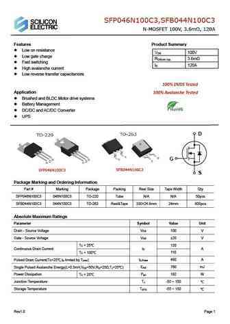
SFP046N100C3,SFB044N100C3 N-MOSFET 100V, 3.6m , 120A Features Product Summary Low on resistance V 100V DS Low gate charge R 3.6m DS(on) typ. Fast switching I 120A D High avalanche current Low reverse transfer capacitances 100% DVDS Tested Application 100% Avalanche Tested Brushed and BLDC Motor drive systems Battery Management DC/DC ... See More ⇒
9.30. Size:1951K cn scilicon
sfp026n100c3 sfb024n100c3.pdf 
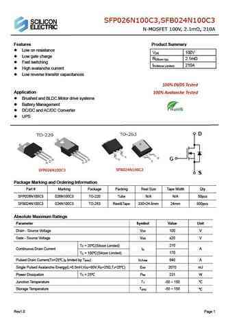
SFP026N100C3,SFB024N100C3 N-MOSFET 100V, 2.1m , 210A Features Product Summary Low on resistance V 100V DS Low gate charge R 2.1m DS(on) typ. Fast switching I 210A D(Silicon Limited) High avalanche current Low reverse transfer capacitances 100% DVDS Tested Application 100% Avalanche Tested Brushed and BLDC Motor drive systems Battery Manage... See More ⇒
9.31. Size:2812K cn scilicon
sfw024n100c3.pdf 

SFW024N100C3 N-MOSFET 100V, 2.0m , 210A Features Product Summary Low on resistance V 100V DS Low gate charge R 2.0m DS(on) typ. Fast switching I 210A D(Silicon Limited) High avalanche current Low reverse transfer capacitances 100% DVDS Tested Application 100% Avalanche Tested Brushed and BLDC Motor drive systems Battery Management DC... See More ⇒
Detailed specifications: 3N80L-TN3-R, 3N80G-TN3-R, 40N15L-TA3-T, 40N15G-TA3-T, 40N15L-TF1-T, 40N15G-TF1-T, 40N15L-TF2-T, 40N15G-TF2-T, IRLZ44N, 4N100G-TA3-T, 4N100L-TF1-T, 4N100G-TF1-T, 4N100L-TF2-T, 4N100G-TF2-T, 4N60KL-TA3-T, 4N60KG-TA3-T, 4N60KL-TF3-T
Keywords - 4N100L-TA3-T MOSFET specs
4N100L-TA3-T cross reference
4N100L-TA3-T equivalent finder
4N100L-TA3-T pdf lookup
4N100L-TA3-T substitution
4N100L-TA3-T replacement
Learn how to find the right MOSFET substitute. A guide to cross-reference, check specs and replace MOSFETs in your circuits.
