AGM40P13S Specs and Replacement
Type Designator: AGM40P13S
Type of Transistor: MOSFET
Type of Control Channel: P-Channel
Absolute Maximum Ratings
Pd ⓘ - Maximum Power Dissipation: 3 W
|Vds|ⓘ - Maximum Drain-Source Voltage: 40 V
|Vgs|ⓘ - Maximum Gate-Source Voltage: 20 V
|Id| ⓘ - Maximum Drain Current: 8 A
Tj ⓘ - Maximum Junction Temperature: 150 °C
Electrical Characteristics
tr ⓘ - Rise Time: 24 nS
Cossⓘ - Output Capacitance: 360 pF
RDSonⓘ - Maximum Drain-Source On-State Resistance: 0.02 Ohm
Package: SOP8
AGM40P13S substitution
- MOSFET ⓘ Cross-Reference Search
AGM40P13S datasheet
agm40p13s.pdf
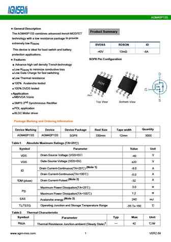
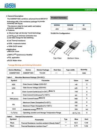
AGM40P13S General Description Product Summary The AGM40P13S combines advanced trench MOSFET to provide technology with a low resistance package extremely low R DS(ON) BVDSS RDSON ID This device is ideal and battery for load switch -40V 13m -8A protection applications. SOP8 Pin Configuration Features Advance high cell density Trench technology Low R to minimize cond... See More ⇒
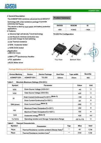
agm40p100h.pdf
AGM40P100H Table 3. Electrical Characteristics (TJ=25 unless otherwise noted) Symbol Parameter Conditions Min Typ Max Unit On/Off States BVDSS Drain-Source Breakdown Voltage V =0V I =-250 A -40 -- -- V GS D Zero Gate Voltage Drain Current V =-40V,V =0V -- -- -1 A DS GS I DSS Gate-Body Leakage Current V = 20V,V =0V -- -- 100 nA GS DS I GSS VGS(th) Gate Threshold Voltage... See More ⇒
agm40p150c.pdf
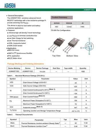
AGM40P150C Table 2. P-Channel Electrical Characteristics (TJ=25 unless otherwisenoted) Symbol Parameter Conditions Min Typ Max Unit On/Off States BVDSS Drain-Source Breakdown Voltage VGS=0V ID=-250 A -40 -- -- V Zero Gate Voltage Drain Current V =-40V,V =0V -1 DS GS I -- -- A DSS Gate-Body Leakage Current V = 40V,V =0V 100 GS DS I -- -- nA GSS V Gate Threshold Voltage V =... See More ⇒
agm40p100a.pdf
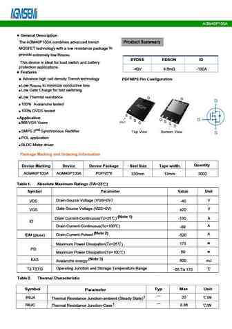
AGM40P100A Typical Electrical And Thermal Characteristics (Curves) Figure 1. Output Characteristics Figure 2. Transfer Characteristics Figure 3. Power Dissipation Figure 4. Drain Current Figure 5. BV vs Junction Temperature Figure 6. R vs Junction Temperature DSS DS(ON) www.agm-mos.com 3 VER2.69 AGM40P100A Figure 7. Gate Charge Waveforms Figure 8. Capacitance Figure 9. Body-... See More ⇒
Detailed specifications: AGM406Q, AGM408M, AGM408MN, AGM409A, AGM409D, AGM40P100A, AGM40P100C, AGM40P100H, 75N75, AGM40P150C, AGM40P25A, AGM40P25AP, AGM40P26AP, AGM40P26E, AGM40P26S, AGM609AP, AGM609C
Keywords - AGM40P13S MOSFET specs
AGM40P13S cross reference
AGM40P13S equivalent finder
AGM40P13S pdf lookup
AGM40P13S substitution
AGM40P13S replacement
Need a MOSFET replacement? Our guide shows you how to find a perfect substitute by comparing key parameters and specs
History: AGM40P150C
🌐 : EN ES РУ

LIST
Last Update
MOSFET: AUN084N10 | AUN065N10 | AUN063N10 | AUN062N08BG | AUN060N08AG | AUN053N10 | AUN050N08BGL | AUN045N085 | AUN042N055 | AUN036N10
Popular searches
2sc1345 | 2sd555 | a950 transistor | k2611 | c1740 transistor | c828 transistor | c4467 | c2383 transistor