GT40. Аналоги и основные параметры
Наименование производителя: GT40
Тип материала: Ge
Полярность: PNP
Предельные значения
Максимальная рассеиваемая мощность (Pc): 0.1 W
Макcимально допустимое напряжение коллектор-база (Ucb): 9 V
Макcимально допустимое напряжение коллектор-эмиттер (Uce): 9 V
Макcимально допустимое напряжение эмиттер-база (Ueb): 6 V
Макcимальный постоянный ток коллектора (Ic): 0.1 A
Предельная температура PN-перехода (Tj): 75 °C
Электрические характеристики
Граничная частота коэффициента передачи тока (ft): 1 MHz
Ёмкость коллекторного перехода (Cc): 15 pf
Статический коэффициент передачи тока (hFE): 15
Корпус транзистора: R145
Аналоги (замена) для GT40
- подборⓘ биполярного транзистора по параметрам
GT40 даташит
0.1. Size:224K 1
gt40qr21.pdf 
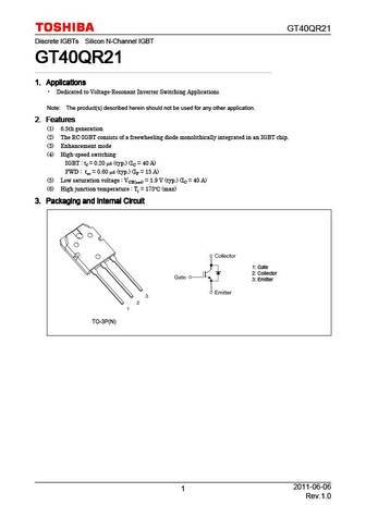
GT40QR21 Discrete IGBTs Silicon N-Channel IGBT GT40QR21 GT40QR21 GT40QR21 GT40QR21 1. Applications 1. Applications 1. Applications 1. Applications Dedicated to Voltage-Resonant Inverter Switching Applications Note The product(s) described herein should not be used for any other application. 2. Features 2. Features 2. Features 2. Features (1) 6.5th generation (2) The RC-IGB
0.2. Size:794K 1
gt40t321.pdf 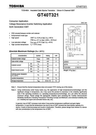
GT40T321 TOSHIBA Insulated Gate Bipolar Transistor Silicon N Channel IGBT GT40T321 Consumer Application Unit mm Voltage Resonance Inverter Switching Application Sixth Generation IGBT FRD included between emitter and collector Enhancement mode type High speed IGBT tf = 0.24 s (typ.) (IC = 40 A) FRD trr = 0.7 s (typ.) (di/dt = -20 A/ s) Low saturation vo
0.3. Size:332K toshiba
gt40j322.pdf 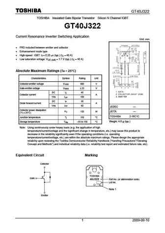
GT40J322 TOSHIBA Insulated Gate Bipolar Transistor Silicon N Channel IGBT GT40J322 Current Resonance Inverter Switching Application Unit mm FRD included between emitter and collector Enhancement mode type High-speed IGBT tf = 0.20 s (typ.) (IC = 40 A) Low saturation voltage VCE (sat) = 1.7 V (typ.) (IC = 40 A) Absolute Maximum Ratings (Ta = 25 C) Charac
0.4. Size:166K toshiba
gt40t301.pdf 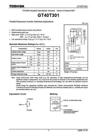
GT40T301 TOSHIBA Insulated Gate Bipolar Transistor Silicon N Channel IGBT GT40T301 Parallel Resonance Inverter Switching Applications Unit mm FRD included between emitter and collector Enhancement mode type High speed IGBT tf = 0.25 s (typ.) (IC = 40 A) FRD trr = 0.7 s (typ.) (di/dt = -20 A/ s) Low saturation voltage VCE (sat) = 3.7 V (typ.) (IC = 40
0.5. Size:251K toshiba
gt40j325.pdf 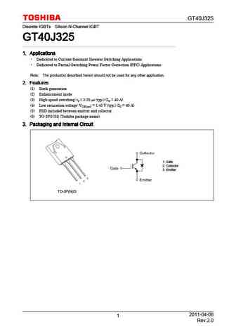
GT40J325 Discrete IGBTs Silicon N-Channel IGBT GT40J325 GT40J325 GT40J325 GT40J325 1. Applications 1. Applications 1. Applications 1. Applications Dedicated to Current-Resonant Inverter Switching Applications Dedicated to Partial-Switching Power Factor Correction (PFC) Applications Note The product(s) described herein should not be used for any other application. 2. Featur
0.6. Size:259K toshiba
gt40m301.pdf 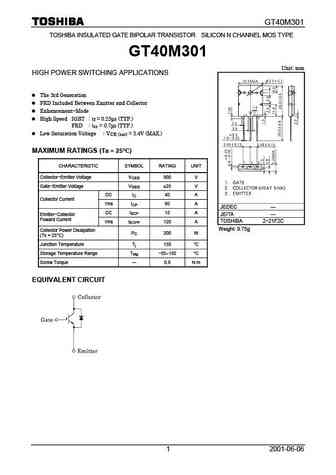
GT40M301 TOSHIBA INSULATED GATE BIPOLAR TRANSISTOR SILICON N CHANNEL MOS TYPE GT40M301 Unit mm HIGH POWER SWITCHING APPLICATIONS The 3rd Generation FRD Included Between Emitter and Collector Enhancement-Mode High Speed IGBT t = 0.25 s (TYP.) f FRD trr = 0.7 s (TYP.) Low Saturation Voltage V = 3.4V (MAX.) CE (sat) MAXIMUM RATINGS (Ta = 25 C) CHARACTE
0.7. Size:327K toshiba
gt40m101.pdf 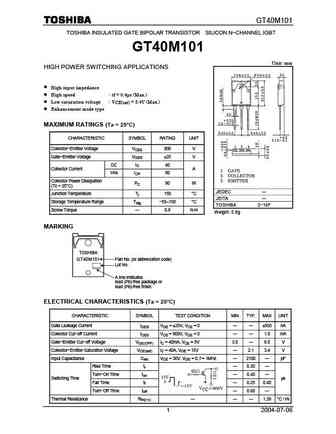
GT40M101 TOSHIBA INSULATED GATE BIPOLAR TRANSISTOR SILICON N-CHANNEL IGBT GT40M101 Unit mm HIGH POWER SWITCHING APPLICATIONS High input impedance High speed tf = 0.4 s (Max.) Low saturation voltage VCE(sat) = 3.4V (Max.) Enhancement mode type MAXIMUM RATINGS (Ta = 25 C) CHARACTERISTIC SYMBOL RATING UNIT Collector-Emitter Voltage VCES 900 V Gate-Emitter Voltage V
0.8. Size:221K toshiba
gt40rr21.pdf 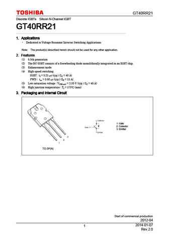
GT40RR21 Discrete IGBTs Silicon N-Channel IGBT GT40RR21 GT40RR21 GT40RR21 GT40RR21 1. Applications 1. Applications 1. Applications 1. Applications Dedicated to Voltage-Resonant Inverter Switching Applications Note The product(s) described herein should not be used for any other application. 2. Features 2. Features 2. Features 2. Features (1) 6.5th generation (2) The RC-IGB
0.9. Size:372K toshiba
gt40j321.pdf 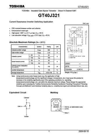
GT40J321 TOSHIBA Insulated Gate Bipolar Transistor Silicon N Channel IGBT GT40J321 Current Resonance Inverter Switching Application Unit mm FRD included between emitter and collector Enhancement mode type High-speed IGBT tf = 0.11 s (typ.) (IC = 40 A) Low saturation voltage VCE (sat) = 2.0 V (typ.) (IC = 40 A) Absolute Maximum Ratings (Ta = 25 C) Charac
0.10. Size:217K toshiba
gt40j121.pdf 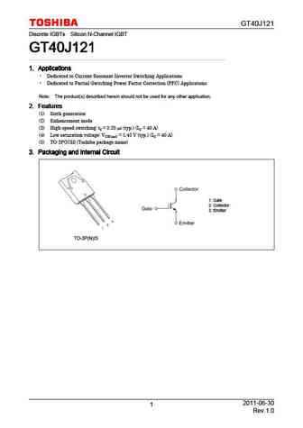
GT40J121 Discrete IGBTs Silicon N-Channel IGBT GT40J121 GT40J121 GT40J121 GT40J121 1. Applications 1. Applications 1. Applications 1. Applications Dedicated to Current-Resonant Inverter Switching Applications Dedicated to Partial-Switching Power Factor Correction (PFC) Applications Note The product(s) described herein should not be used for any other application. 2. Featur
0.11. Size:381K toshiba
gt40wr21.pdf 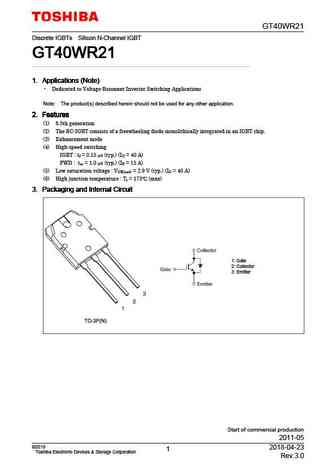
GT40WR21 Discrete IGBTs Silicon N-Channel IGBT GT40WR21 GT40WR21 GT40WR21 GT40WR21 1. Applications (Note) 1. Applications (Note) 1. Applications (Note) 1. Applications (Note) Dedicated to Voltage-Resonant Inverter Switching Applications Note The product(s) described herein should not be used for any other application. 2. Features 2. Features 2. Features 2. Features (1) 6.5t
0.12. Size:805K rohm
rgt40ns65d.pdf 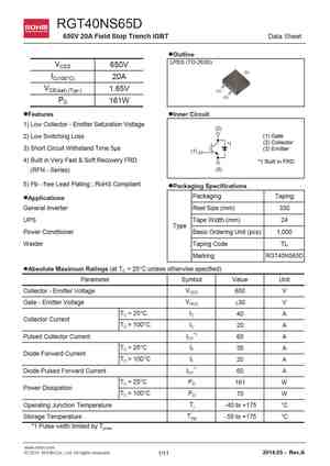
RGT40NS65D 650V 20A Field Stop Trench IGBT Data Sheet lOutline LPDS (TO-263S) VCES 650V (2) IC(100 C) 20A VCE(sat) (Typ.) 1.65V (1) (3) PD 161W lFeatures lInner Circuit 1) Low Collector - Emitter Saturation Voltage (2) (1) Gate 2) Low Switching Loss (2) Collector *1 3) Short Circuit Withstand Time 5 s (3) Emitter (1) 4) Built in Very Fast & Soft Recovery FR
0.13. Size:743K rohm
rgt40ts65d.pdf 
RGT40TS65D 650V 20A Field Stop Trench IGBT Data Sheet lOutline TO-247N VCES 650V IC(100 C) 20A VCE(sat) (Typ.) 1.65V PD 144W (1)(2)(3) lFeatures lInner Circuit 1) Low Collector - Emitter Saturation Voltage (2) (1) Gate 2) Low Switching Loss (2) Collector *1 3) Short Circuit Withstand Time 5 s (3) Emitter (1) 4) Built in Very Fast & Soft Recovery FRD *1 Built i
0.14. Size:155K vishay
vs-gt400th60n.pdf 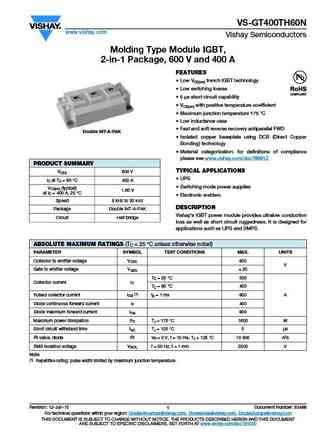
VS-GT400TH60N www.vishay.com Vishay Semiconductors Molding Type Module IGBT, 2-in-1 Package, 600 V and 400 A FEATURES Low VCE(on) trench IGBT technology Low switching losses 5 s short circuit capability VCE(on) with positive temperature coefficient Maximum junction temperature 175 C Low inductance case Fast and soft reverse recovery antiparallel FWD
0.15. Size:127K vishay
vs-gt400th120n.pdf 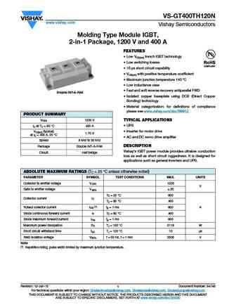
VS-GT400TH120N www.vishay.com Vishay Semiconductors Molding Type Module IGBT, 2-in-1 Package, 1200 V and 400 A FEATURES Low VCE(on) trench IGBT technology Low switching losses 10 s short circuit capability VCE(on) with positive temperature coefficient Maximum junction temperature 150 C Low inductance case Fast and soft reverse recovery antiparallel FW
0.16. Size:292K vishay
vs-gt400th120u.pdf 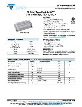
VS-GT400TH120U www.vishay.com Vishay Semiconductors Molding Type Module IGBT, 2-in-1 Package, 1200 V, 400 A FEATURES Low VCE(on) trench IGBT technology 10 s short circuit capability VCE(on) with positive temperature coefficient Maximum junction temperature 175 C Low inductance case Fast and soft reverse recovery antiparallel FWD Isolated copper basepl
0.17. Size:162K ixys
ixgh40n60c2d1 ixgt40n60c2d1 ixgg40n60c2d1.pdf 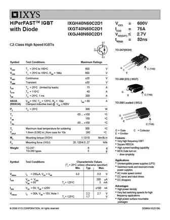
HiPerFASTTM IGBT IXGH40N60C2D1 VCES = 600V IXGT40N60C2D1 IC25 = 75A with Diode IXGJ40N60C2D1 VCE(SAT) 2.7V tfi(typ) = 32ns C2-Class High Speed IGBTs TO-247(IXGH) Symbol Test Conditions Maximum Ratings G VCES TJ = 25 C to 150 C 600 V C (TAB) C E VCGR TJ = 25 C to 150 C, RGE = 1M 600 V VGES Continuous 20 V TO-268 (D3) ( IXGT) VGEM Transient 30 V
0.18. Size:291K ixys
ixgh40n60b ixgt40n60b.pdf 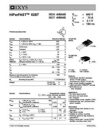
IXGH 40N60B VCES = 600 V HiPerFASTTM IGBT IXGT 40N60B IC25 = 75 A VCE(sat) = 2.1 V tfi = 180 ns Preliminary data sheet Symbol Test Conditions Maximum Ratings TO-247 AD (IXGH) VCES TJ = 25 C to 150 C 600 V VCGR TJ = 25 C to 150 C; RGE = 1 MW 600 V C (TAB) VGES Continuous 20 V G C VGEM Transient 30 V E IC25 TC = 25 C75 A IC110 TC = 110 C40 A TO-268 (D3) ICM TC = 25 C
0.19. Size:168K ixys
ixgt40n120a2.pdf 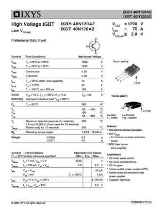
IXGH 40N120A2 IXGT 40N120A2 IXGH 40N120A2 VCES = 1200 V High Voltage IGBT IXGT 40N120A2 IC25 = 75 A Low VCE(sat) VCE(sat) 2.0 V Preliminary Data Sheet Symbol Test Conditions Maximum Ratings TO-247 (IXFH) VCES TJ = 25 C to 150 C 1200 V VCES TJ = 25 C to 150 C 1200 V VGES Continuous 20 V VGEM Transient 30 V G C IC25 TC = 25 C, IGBT chip capabilit
0.20. Size:575K ixys
ixgt40n60b2.pdf 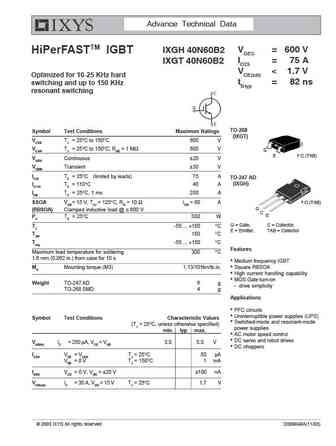
Advance Technical Data VCES = 600 V IXGH 40N60B2 HiPerFASTTM IGBT IC25 = 75 A IXGT 40N60B2 VCE(sat)
0.21. Size:168K ixys
ixgt40n60c2d1.pdf 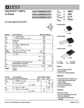
HiPerFASTTM IGBTs VCES = 600V IXGT40N60C2D1 IC110 = 40A w/ Diode IXGJ40N60C2D1 VCE(SAT) 2.7V IXGH40N60C2D1 tfi(typ) = 32ns C2-Class High Speed IGBTs TO-268 (IXGT) G E C (Tab) Symbol Test Conditions Maximum Ratings TO-268 (IXGJ) VCES TJ = 25 C to 150 C 600 V VCGR TJ = 25 C to 150 C, RGE = 1M 600 V VGES Continuous 20 V G VGEM Transient 30 V
0.22. Size:513K ixys
ixgt40n60b2d1.pdf 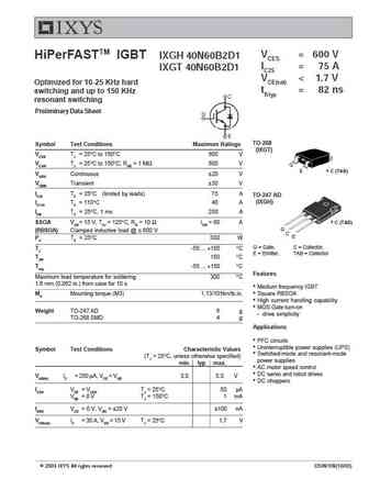
VCES = 600 V HiPerFASTTM IGBT IXGH 40N60B2D1 IC25 = 75 A IXGT 40N60B2D1 VCE(sat)
0.23. Size:122K ixys
ixgt40n60c.pdf 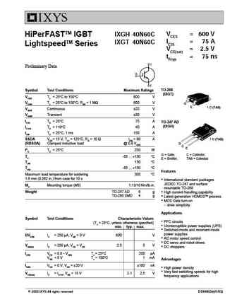
VCES = 600 V IXGH 40N60C HiPerFASTTM IGBT IC25 = 75 A IXGT 40N60C LightspeedTM Series VCE(sat) = 2.5 V tfi typ = 75 ns Preliminary Data TO-268 Symbol Test Conditions Maximum Ratings (IXGT) VCES TJ = 25 C to 150 C 600 V VCGR TJ = 25 C to 150 C; RGE = 1 M 600 V G E C (TAB) VGES Continuous 20 V VGEM Transient 30 V IC25 TC = 25 C75 A TO-247 AD (IXGH) IC110 TC = 11
0.25. Size:149K ixys
ixgh40n60c2 ixgt40n60c2.pdf 
VCES = 600 V IXGH 40N60C2 HiPerFASTTM IGBT IC25 = 75 A IXGT 40N60C2 C2-Class High Speed IGBTs VCE(sat) = 2.7 V tfi typ = 32 ns TO-268 (IXGT) Symbol Test Conditions Maximum Ratings VCES TJ = 25 C to 150 C 600 V G VCGR TJ = 25 C to 150 C; RGE = 1 M 600 V E C (TAB) VGES Continuous 20 V VGEM Transient 30 V TO-247 (IXGH) IC25 TC = 25 C (limited by leads) 75 A IC110 TC = 1
0.26. Size:145K ixys
ixgt40n60c2.pdf 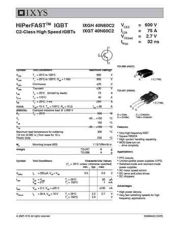
VCES = 600 V IXGH 40N60C2 HiPerFASTTM IGBT IC25 = 75 A IXGT 40N60C2 C2-Class High Speed IGBTs VCE(sat) = 2.7 V tfi typ = 32 ns TO-268 (IXGT) Symbol Test Conditions Maximum Ratings VCES TJ = 25 C to 150 C 600 V G VCGR TJ = 25 C to 150 C; RGE = 1 M 600 V E C (TAB) VGES Continuous 20 V VGEM Transient 30 V TO-247 (IXGH) IC25 TC = 25 C (limited by leads) 75 A IC110 TC = 1
0.27. Size:578K ixys
ixgh40n60b2 ixgt40n60b2.pdf 
Advance Technical Data VCES = 600 V IXGH 40N60B2 HiPerFASTTM IGBT IC25 = 75 A IXGT 40N60B2 VCE(sat)
0.28. Size:213K ixys
ixgt40n120b2d1.pdf 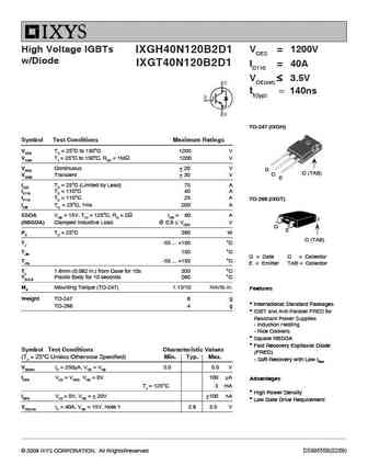
High Voltage IGBTs VCES = 1200V IXGH40N120B2D1 w/Diode IXGT40N120B2D1 IC110 = 40A VCE(sat) 3.5V tfi(typ) = 140ns TO-247 (IXGH) Symbol Test Conditions Maximum Ratings VCES TC = 25 C to 150 C 1200 V VCGR TJ = 25 C to 150 C, RGE = 1M 1200 V VGES Continuous 20 V G C (TAB) C VGEM Transient 30 V E IC25 TC = 25 C (Limited by Lead) 75 A IC110 TC =
0.29. Size:189K apt
aptgt400u120d4.pdf 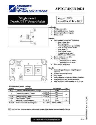
APTGT400U120D4 VCES = 1200V Single switch IC = 400A @ Tc = 80 C Trench IGBT Power Module Application Welding converters 1 Switched Mode Power Supplies Uninterruptible Power Supplies Motor control 3 Features 5 Trench + Field Stop IGBT Technology - Low voltage drop 2 - Low tail current - Switching frequency up to 20 kHz - Soft recovery par
0.30. Size:189K apt
aptgt400u170d4.pdf 
APTGT400U170D4 VCES = 1700V Single switch IC = 400A @ Tc = 80 C Trench IGBT Power Module Application Welding converters 1 Switched Mode Power Supplies Uninterruptible Power Supplies Motor control 3 Features 5 Trench + Field Stop IGBT Technology - Low voltage drop 2 - Low tail current - Switching frequency up to 20 kHz - Soft recovery par
0.31. Size:429K kec
kgt40n60kda.pdf 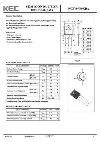
SEMICONDUCTOR KGT40N60KDA TECHNICAL DATA General Description B A KEC NPT Trench IGBTs offer low switching losses, high energy efficiency O S K and short circuit ruggedness. It is designed for applications such as motor control, uninterrupted power supplies(UPS), general inverters. DIM MILLIMETERS _ + A 15.90 0.30 _ B 5.00 + 0.20 _ FEATURES C 20.85 + 0.30 _ D 3.00 + 0.20
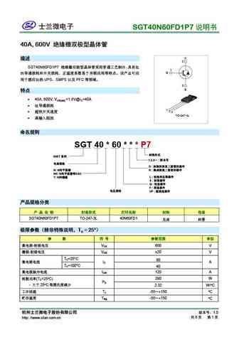
0.37. Size:273K silan
sgt40n60f2p7.pdf 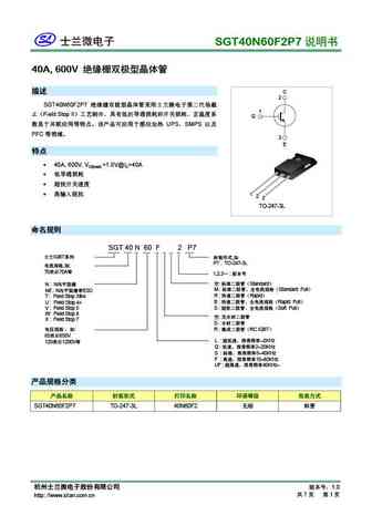
SGT40N60F2P7 40A, 600V C 2 SGT40N60F2P7 1 Field Stop II G UPS SMPS PFC 3 E 4
0.39. Size:314K silan
sgt40t120sdb4p7.pdf 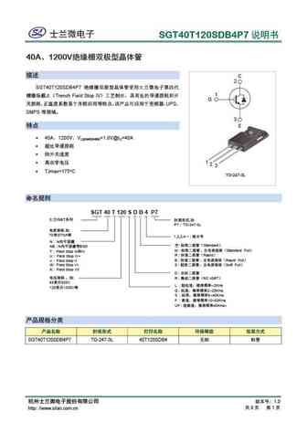
SGT40T120SDB4P7 40A 1200V C 2 SGT40T120SDB4P7 1 Trench Field Stop IV G UPS SMPS 3 E
0.40. Size:367K silan
sgt40u120fd1p7.pdf 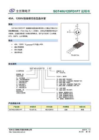
SGT40U120FD1P7 40A 1200V C 2 SGT40U120FD1P7 1 Field Stop 4+ G UPS SMPS
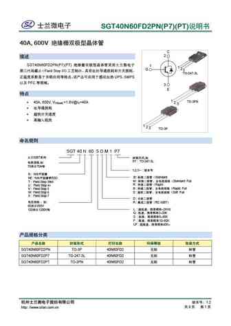
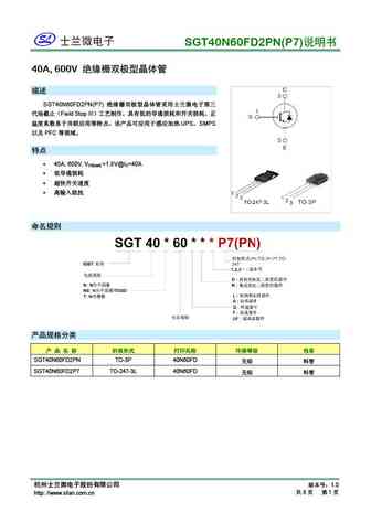
0.41. Size:293K silan
sgt40n60npfdpn.pdf 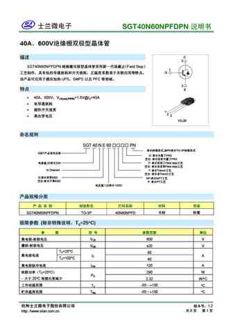
SGT40N60NPFDPN 40A 600V C 2 SGT40N60NPFDPN Field Stop 1 G UPS SMPS PFC 3 E 40A 600V
0.43. Size:161K macmic
mmgt40h120xb6c.pdf 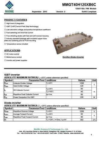
MMGT40H120XB6C 1200V 40A PIM Module September 2015 Version 0 RoHS Compliant PRODUCT FEATURES High level of integration IGBT CHIP(Trench+Field Stop technology) Low saturation voltage and positive temperature coefficient Fast switching and short tail current Free wheeling diodes with fast and soft reverse recovery Industry standard package with insulated copper ba
Другие транзисторы: GT362B, GT376A, GT383A, GT383A-2, GT383B, GT383B-2, GT383V, GT383V-2, 2N3906, GT400-10A, GT400-10B, GT400-10C, GT400-10D, GT400-10E, GT400-3A, GT400-3B, GT400-3C