View fir10n60fg detailed specification:
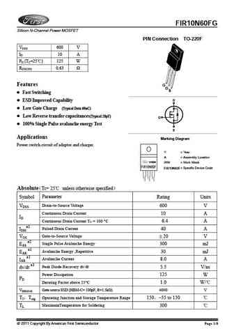
FIR10N60FG Silicon N-Channel Power MOSFET PIN Connection TO-220F VDSS 600 V ID 10 A PD (TC=25 ) 125 W RDS(ON) 0.63 Features G D S Fast Switching ESD Improved Capability D Low Gate Charge (Typical Data 60nC) Low Reverse transfer capacitances(Typical 28pF) G 100% Single Pulse avalanche energy Test S Applications Marking Diagram Power switch circuit of adaptor and charger. Y = Year A = Assembly Location YAWW WW = Work Week FIR10N60F FIR10N60F = Specific Device Code Absolute Tc= 25 unless otherwise specified Symbol Parameter Rating Units Drain-to-Source Voltage VDSS 600 V Continuous Drain Current 10 A ID Continuous Drain Current TC = 100 C 6.4 A a1 40 A IDM Pulsed Drain Current Gate-to-Source Voltage VGS 20 V a2 300 mJ EAS Single Pulse Avalanche Energy a1 30 mJ EAR Avalanche Energy ,Repetitiv... See More ⇒
Keywords - ALL TRANSISTORS SPECS
fir10n60fg.pdf Design, MOSFET, Power
fir10n60fg.pdf RoHS Compliant, Service, Triacs, Semiconductor
fir10n60fg.pdf Database, Innovation, IC, Electricity
BJT Parameters and How They Relate
🌐 : EN ES РУ

LIST
Last Update
BJT: ZDT6705 | GA1L4Z | GA1A4M | SBT42 | 2SA200-Y | 2SA200-O
Popular searches
irfz44n | irf3205 | irfz44n datasheet | 2n4401 | bc547 transistor | bd139 | 2n4401 datasheet