SSF4624 MOSFET Equivalente. Reemplazo. Hoja de especificaciones. Principales características
Número de Parte: SSF4624
Tipo de FET: MOSFET
Polaridad de transistor: N
ESPECIFICACIONES MÁXIMAS
Pdⓘ - Máxima disipación de potencia: 2 W
|Vds|ⓘ - Voltaje máximo drenador-fuente: 40 V
|Vgs|ⓘ - Voltaje máximo fuente-puerta: 20 V
|Id|ⓘ - Corriente continua de drenaje: 6 A
Tjⓘ - Temperatura máxima de unión: 150 °C
CARACTERÍSTICAS ELÉCTRICAS
trⓘ - Tiempo de subida: 3 nS
Cossⓘ - Capacitancia de salida: 95 pF
RDSonⓘ - Resistencia estado encendido drenaje a fuente: 0.031 Ohm
Encapsulados: SOP8
Búsqueda de reemplazo de SSF4624 MOSFET
- Selecciónⓘ de transistores por parámetros
SSF4624 datasheet
ssf4624.pdf
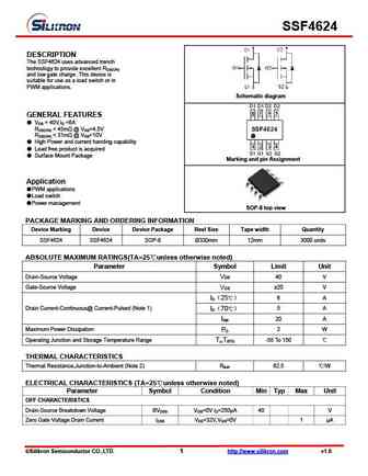
SSF4624 DESCRIPTION The SSF4624 uses advanced trench technology to provide excellent RDS(ON) and low gate charge .This device is suitable for use as a load switch or in PWM applications. Schematic diagram GENERAL FEATURES VDS = 40V,ID =6A RDS(ON)
ssf4607d.pdf
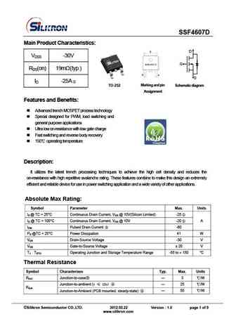
SSF4607D Main Product Characteristics D VDSS -30V G RDS(on) 19m (typ.) S ID -25A TO-252 Marking and pin Schematic diagram Ass ig nme nt Features and Benefits Advanced trench MOSFET process technology Special designed for PWM, load switching and general purpose applications Ultra low on-resistance with low gate charge Fast switching and reverse
ssf4606.pdf
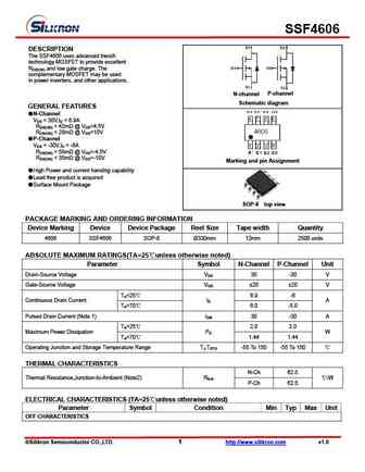
SSF4606 DESCRIPTION The SSF4606 uses advanced trench technology MOSFET to provide excellent RDS(ON) and low gate charge. The complementary MOSFET may be used in power inverters, and other applications. P-channel N-channel Schematic diagram GENERAL FEATURES N-Channel VDS = 30V,ID = 6.9A RDS(ON)
ssf4604.pdf
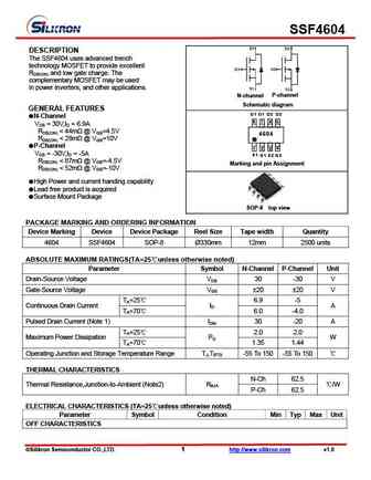
SSF4604 DESCRIPTION The SSF4604 uses advanced trench technology MOSFET to provide excellent RDS(ON) and low gate charge. The complementary MOSFET may be used in power inverters, and other applications. P-channel N-channel Schematic diagram GENERAL FEATURES D1 D1 D2 D2 N-Channel 8 7 6 5 VDS = 30V,ID = 6.9A RDS(ON)
Otros transistores... SSF4015, SSF4031C1, SSF4032CH3, SSF4203, SSF4414, SSF4604, SSF4606, SSF4607D, IRF3710, SSF4703, SSF4703DC, SSF47NS60H, SSF4953, SSF4N60, SSF4N60D, SSF4N60F, SSF4N60G
🌐 : EN ES РУ

Liste
Recientemente añadidas las descripciónes de los transistores:
MOSFET: FTF30P35D | FTF25N35DHVT | FTF15N35D | FTE15C35G | FTP02P15G | FTE02P15G | AKF30N5P0SX | AKF30N10S | AKF20P45D | CM4407 | CM3407 | CM3400 | SVF11N65F | SVF11N65T | FKBB3105 | EHBA036R1
Popular searches
2sc2291 | bc139 | 2sc1398 | 2sd218 | bc547 характеристики | me15n10-g | 2n2905 equivalent | 2sa640