GD1 MOSFET Equivalente. Reemplazo. Hoja de especificaciones. Principales características
Número de Parte: GD1
Tipo de FET: MOSFET
Polaridad de transistor: P
ESPECIFICACIONES MÁXIMAS
Pdⓘ - Máxima disipación de potencia: 0.9 W
|Vds|ⓘ - Voltaje máximo drenador-fuente: 20 V
|Vgs|ⓘ - Voltaje máximo fuente-puerta: 12 V
|Id|ⓘ - Corriente continua de drenaje: 2.6 A
Tjⓘ - Temperatura máxima de unión: 150 °C
CARACTERÍSTICAS ELÉCTRICAS
trⓘ - Tiempo de subida: 35 nS
Cossⓘ - Capacitancia de salida: 130 pF
RDSonⓘ - Resistencia estado encendido drenaje a fuente: 0.11 Ohm
Encapsulados: SOT23
Búsqueda de reemplazo de GD1 MOSFET
- Selecciónⓘ de transistores por parámetros
GD1 datasheet
gd1.pdf
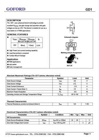
GOFORD GD1 DESCRIPTION D The GD1 uses advanced trench technology to provide excellent RDS(ON), low gate charge and operation with gate G voltages as low as 2.5V. This device is suitable for use as a load switch or in PWM applications. S GENERAL FEATURES Schematic diagram VDSS RDS(ON) RDS(ON) ID (Typ) @-2.5V @-4.5V (Typ) -20V 88m 110m -2.6 A GD1 High P
ngd18n40clb.pdf

NGD18N40CLB, NGD18N40ACLB Ignition IGBT, 18 A, 400 V N-Channel DPAK This Logic Level Insulated Gate Bipolar Transistor (IGBT) features monolithic circuitry integrating ESD and Over-Voltage clamped http //onsemi.com protection for use in inductive coil drivers applications. Primary uses include Ignition, Direct Fuel Injection, or wherever high voltage and 18 AMPS, 400 VOLTS high curren
stgd18n40lz.pdf

STGB18N40LZ STGD18N40LZ, STGP18N40LZ EAS 180 mJ - 390 V - internally clamped IGBT Features AEC Q101 compliant 3 3 2 180 mJ of avalanche energy @ TC = 150 C, 1 1 L = 3 mH DPAK IPAK ESD gate-emitter protection Gate-collector high voltage clamping 3 Logic level gate drive 2 1 Low saturation voltage TO-220 3 1 High pulsed current capability 3
stgd10nc60sd.pdf
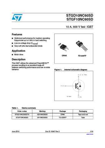
STGD10NC60SD STGF10NC60SD 10 A, 600 V fast IGBT Features Optimized performance for medium operating frequencies up to 5 kHz in hard switching Low on-voltage drop (VCE(sat)) Very soft ultra fast antiparallel diode 3 3 2 1 Application 1 Motor drive DPAK TO-220FP Description This IGBT utilizes the advanced PowerMESH process resulting in an excellent trade-of
stgd10nc60kd.pdf
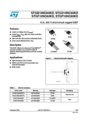
STGB10NC60KD, STGD10NC60KD STGF10NC60KD, STGP10NC60KD 10 A, 600 V short-circuit rugged IGBT Features TAB TAB Lower on voltage drop (VCE(sat)) 3 Lower CRES / CIES ratio (no cross-conduction 1 3 1 susceptibility) DPAK Very soft ultra fast recovery antiparallel diode D2PAK TAB Short-circuit withstand time 10 s Description This IGBT utilizes the advanced PowerM
stgb10nc60kd stgd10nc60kd stgf10nc60kd stgp10nc60kd.pdf

STGB10NC60KD, STGD10NC60KD STGF10NC60KD, STGP10NC60KD 10 A, 600 V short-circuit rugged IGBT Features TAB TAB Lower on voltage drop (VCE(sat)) 3 Lower CRES / CIES ratio (no cross-conduction 1 3 1 susceptibility) DPAK Very soft ultra fast recovery antiparallel diode D2PAK TAB Short-circuit withstand time 10 s Description This IGBT utilizes the advanced PowerM
stgd10nc60h.pdf
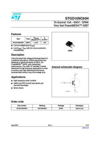
STGD10NC60H N-channel 10A - 600V - DPAK Very fast PowerMESH IGBT Features VCE(sat) IC VCES Type (Max)@ 25 C @100 C STGD10NC60H 600V
stgd10nc60s.pdf
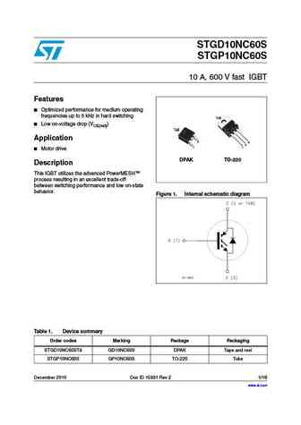
STGD10NC60S STGP10NC60S 10 A, 600 V fast IGBT Features Optimized performance for medium operating frequencies up to 5 kHz in hard switching TAB Low on-voltage drop (VCE(sat)) TAB Application 3 3 2 1 1 Motor drive DPAK TO-220 Description This IGBT utilizes the advanced PowerMESH process resulting in an excellent trade-off between switching performance and low
stgb18n40lz stgd18n40lz stgp18n40lz.pdf
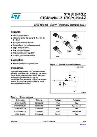
STGB18N40LZ STGD18N40LZ, STGP18N40LZ EAS 180 mJ - 390 V - internally clamped IGBT Features AEC Q101 compliant 3 3 2 180 mJ of avalanche energy @ TC = 150 C, 1 1 L = 3 mH DPAK IPAK ESD gate-emitter protection Gate-collector high voltage clamping 3 Logic level gate drive 2 1 Low saturation voltage TO-220 3 1 High pulsed current capability 3
stgb10nc60k stgp10nc60k stgd10nc60k.pdf
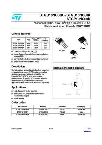
STGB10NC60K - STGD10NC60K STGP10NC60K N-channel 600V - 10A - D2PAK / TO-220 / DPAK Short circuit rated PowerMESH IGBT General features IC VCE(sat)Max Type VCES @25 C @100 C STGB10NC60K 600V
stgd10nc60sd stgf10nc60sd.pdf

STGD10NC60SD STGF10NC60SD 10 A, 600 V fast IGBT Features Optimized performance for medium operating frequencies up to 5 kHz in hard switching Low on-voltage drop (VCE(sat)) Very soft ultra fast antiparallel diode 3 3 2 1 Application 1 Motor drive DPAK TO-220FP Description This IGBT utilizes the advanced PowerMESH process resulting in an excellent trade-of
stgd10hf60kd.pdf
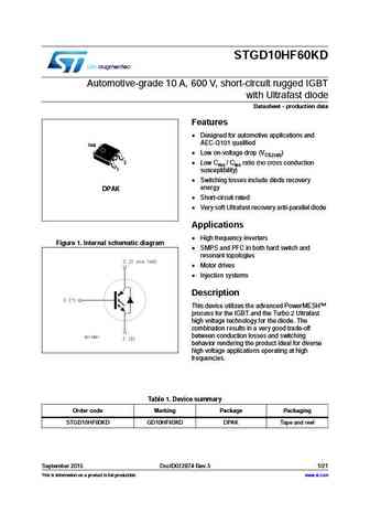
STGD10HF60KD Automotive-grade 10 A, 600 V, short-circuit rugged IGBT with Ultrafast diode Datasheet - production data Features Designed for automotive applications and AEC-Q101 qualified TAB Low on-voltage drop (VCE(sat)) 3 Low Cres / Cies ratio (no cross conduction 1 susceptibility) Switching losses include diode recovery energy DPAK Short-circuit rated
stgb10nc60kdt4 stgd10nc60kdt4 stgf10nc60kd stgp10nc60kd.pdf
STGB10NC60KDT4, STGD10NC60KDT4, STGF10NC60KD, STGP10NC60KD 10 A, 600 V short-circuit rugged IGBT Datasheet - production data Features Lower on voltage drop (V ) CE(sat) Lower C / C ratio (no cross-conduction RES IES susceptibility) Very soft ultra fast recovery antiparallel diode Short-circuit withstand time 10 s Applications High frequency motor
stgd10nc60s stgp10nc60s.pdf
STGD10NC60S STGP10NC60S 10 A - 600 V fast IGBT Features Very low on-voltage drop (VCE(sat)) Minimum power losses at 5 kHz in hard switching Optimized performance for medium operating frequencies 3 3 2 1 1 Application DPAK TO-220 Medium frequency motor control Description This IGBT utilizes the advanced PowerMESH process resulting in an excellent trade-of
stgb14nc60k stgd14nc60k.pdf

STGB14NC60K STGD14NC60K N-channel 14A - 600V -DPAK - D2PAK Short circuit rated PowerMESH IGBT General features IC VCE(sat) Type VCES (Max)@ 25 C @100 C STGB14NC60K 600V
stgd19n40lz.pdf
STGD19N40LZ Automotive-grade 390 V internally clamped IGBT ESCIS 180 mJ Datasheet - production data Features Designed for automotive applications and AEC-Q101 qualified TAB 180 mJ of avalanche energy @ TC = 150 C, L = 3 mH 3 ESD gate-emitter protection 1 Gate-collector high voltage clamping Logic level gate drive DPAK Low saturation voltage Hig
stgb18n40lzt4 stgd18n40lz stgp18n40lz.pdf
STGB18N40LZT4, STGD18N40LZ, STGP18N40LZ Automotive-grade 390 V internally clamped IGBT ESCIS 180 mJ Datasheet - production data Features TAB TAB Designed for automotive applications and 3 AEC-Q101 qualified 3 1 2 1 180 mJ of avalanche energy @ TC = 150 C, DPAK L = 3 mH IPAK ESD gate-emitter protection TAB Gate-collector high voltage clamping TAB
stgd10nc60hd.pdf
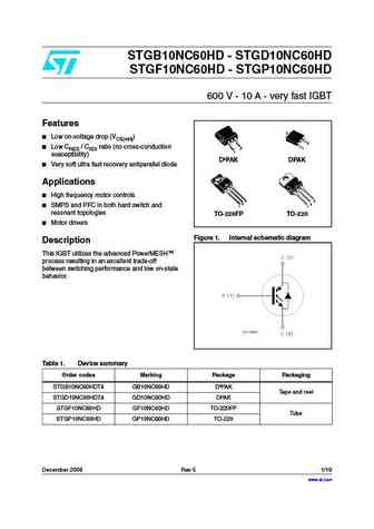
STGB10NC60HD - STGD10NC60HD STGF10NC60HD - STGP10NC60HD 600 V - 10 A - very fast IGBT Features 2 Low on-voltage drop (VCE(sat)) 3 Low CRES / CIES ratio (no cross-conduction 3 1 1 susceptibility) D PAK DPAK Very soft ultra fast recovery antiparallel diode Applications High frequency motor controls 3 3 2 2 SMPS and PFC in both hard switch and 1 1 resonant
stgd14nc60k.pdf
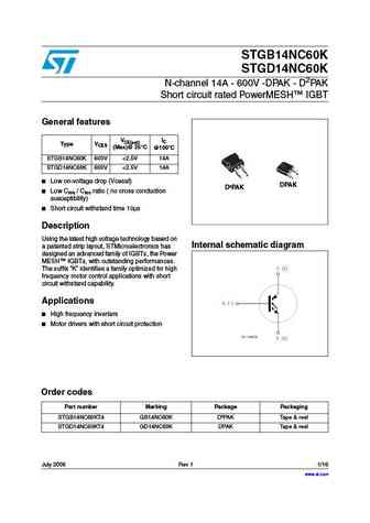
STGB14NC60K STGD14NC60K N-channel 14A - 600V -DPAK - D2PAK Short circuit rated PowerMESH IGBT General features IC VCE(sat) Type VCES (Max)@ 25 C @100 C STGB14NC60K 600V
stgb10nc60hd stgd10nc60hd stgf10nc60hd stgp10nc60hd.pdf

STGB10NC60HD - STGD10NC60HD STGF10NC60HD - STGP10NC60HD 600 V - 10 A - very fast IGBT Features 2 Low on-voltage drop (VCE(sat)) 3 Low CRES / CIES ratio (no cross-conduction 3 1 1 susceptibility) D PAK DPAK Very soft ultra fast recovery antiparallel diode Applications High frequency motor controls 3 3 2 2 SMPS and PFC in both hard switch and 1 1 resonant
pmgd130un.pdf
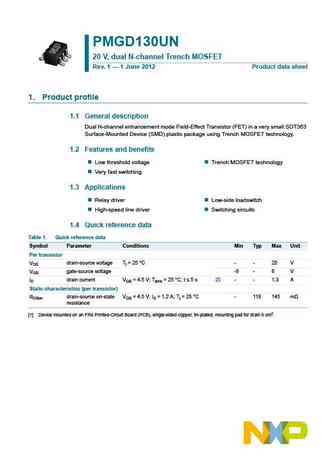
PMGD130UN 20 V, dual N-channel Trench MOSFET Rev. 1 1 June 2012 Product data sheet 1. Product profile 1.1 General description Dual N-channel enhancement mode Field-Effect Transistor (FET) in a very small SOT363 Surface-Mounted Device (SMD) plastic package using Trench MOSFET technology. 1.2 Features and benefits Low threshold voltage Trench MOSFET technology Very fast
pmgd175xn.pdf
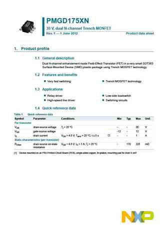
PMGD175XN 30 V, dual N-channel Trench MOSFET Rev. 1 1 June 2012 Product data sheet 1. Product profile 1.1 General description Dual N-channel enhancement mode Field-Effect Transistor (FET) in a very small SOT363 Surface-Mounted Device (SMD) plastic package using Trench MOSFET technology. 1.2 Features and benefits Very fast switching Trench MOSFET technology 1.3 Applications
ngd18n45.pdf

NGD18N45CLB Ignition IGBT 18 Amps, 450 Volts N-Channel DPAK This Logic Level Insulated Gate Bipolar Transistor (IGBT) features monolithic circuitry integrating ESD and Over-Voltage clamped http //onsemi.com protection for use in inductive coil drivers applications. Primary uses include Ignition, Direct Fuel Injection, or wherever high voltage and 18 AMPS high current switching is requ
ngd15n41a.pdf
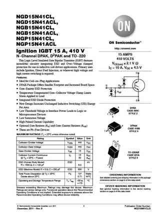
NGD15N41CL, NGD15N41ACL, NGB15N41CL, NGB15N41ACL, NGP15N41CL, NGP15N41ACL http //onsemi.com Ignition IGBT 15 A, 410 V 15 AMPS N-Channel DPAK, D2PAK and TO-220 410 VOLTS This Logic Level Insulated Gate Bipolar Transistor (IGBT) features VCE(on) 3 2.1 V @ monolithic circuitry integrating ESD and Over-Voltage clamped protection for use in inductive coil drivers applications. Primary
ngd18n40a.pdf
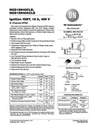
NGD18N40CLB, NGD18N40ACLB Ignition IGBT, 18 A, 400 V N-Channel DPAK This Logic Level Insulated Gate Bipolar Transistor (IGBT) features monolithic circuitry integrating ESD and Over-Voltage clamped http //onsemi.com protection for use in inductive coil drivers applications. Primary uses include Ignition, Direct Fuel Injection, or wherever high voltage and 18 AMPS, 400 VOLTS high curren
ngd18n45clbt4g.pdf
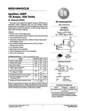
NGD18N45CLB Ignition IGBT 18 Amps, 450 Volts N-Channel DPAK This Logic Level Insulated Gate Bipolar Transistor (IGBT) features monolithic circuitry integrating ESD and Over-Voltage clamped http //onsemi.com protection for use in inductive coil drivers applications. Primary uses include Ignition, Direct Fuel Injection, or wherever high voltage and 18 AMPS high current switching is requ
ntgd1100l.pdf
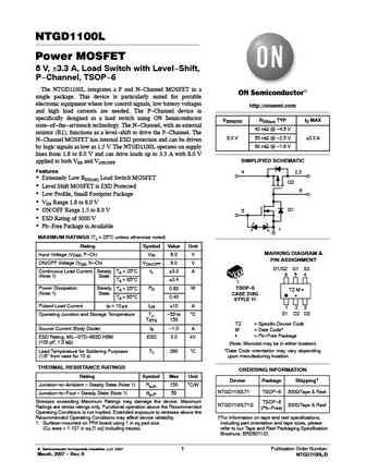
NTGD1100L Power MOSFET 8 V, 3.3 A, Load Switch with Level-Shift, P-Channel, TSOP-6 The NTGD1100L integrates a P and N-Channel MOSFET in a single package. This device is particularly suited for portable electronic equipment where low control signals, low battery voltages http //onsemi.com and high load currents are needed. The P-Channel device is specifically designed as a load switch
ngd15n41cl ngb15n41cl ngp15n41cl.pdf
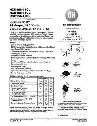
NGD15N41CL, NGB15N41CL, NGP15N41CL Preferred Device Ignition IGBT 15 Amps, 410 Volts http //onsemi.com N-Channel DPAK, D2PAK and TO-220 15 AMPS This Logic Level Insulated Gate Bipolar Transistor (IGBT) features monolithic circuitry integrating ESD and Over-Voltage clamped 410 VOLTS protection for use in inductive coil drivers applications. Primary uses VCE(on) 3 2.1 V @ include I
bsm35gd120dn2 bsm35gd120dn2 e3224.pdf

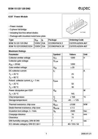
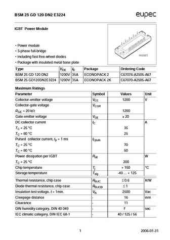
BSM 35 GD 120 DN2 IGBT Power Module Power module 3-phase full-bridge Including fast free-wheel diodes Package with insulated metal base plate Type VCE IC Package Ordering Code BSM 35 GD 120 DN2 1200V 50A ECONOPACK 2 C67076-A2506-A67 BSM35GD120DN2E3224 1200V 50A ECONOPACK 2K C67070-A2506-A67 Maximum Ratings Parameter Symbol Values Unit Collector-emitter voltage VCE 120
bsm10gd120dn2.pdf
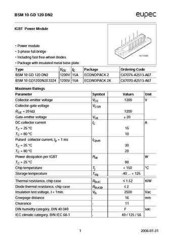
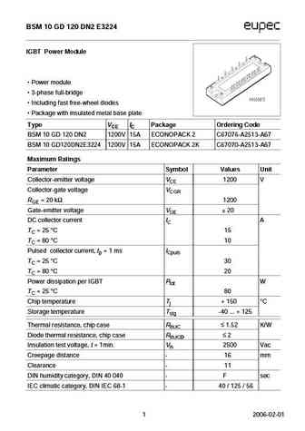
BSM 10 GD 120 DN2 IGBT Power Module Power module 3-phase full-bridge Including fast free-wheel diodes Package with insulated metal base plate Type VCE IC Package Ordering Code BSM 10 GD 120 DN2 1200V 15A ECONOPACK 2 C67076-A2513-A67 BSM 10 GD120DN2E3224 1200V 15A ECONOPACK 2K C67070-A2513-A67 Maximum Ratings Parameter Symbol Values Unit Collector-emitter voltage VCE 1
bsm50gd120dn2.pdf
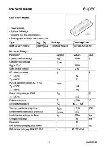
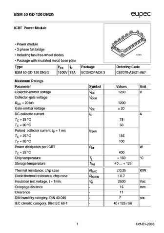
BSM 50 GD 120 DN2 IGBT Power Module Power module 3-phase full-bridge Including fast free-wheel diodes Package with insulated metal base plate Type VCE IC Package Ordering Code BSM 50 GD 120 DN2 1200V 72A ECONOPACK 2K C67076-A2514-A67 Maximum Ratings Parameter Symbol Values Unit Collector-emitter voltage VCE 1200 V Collector-gate voltage VCGR RGE = 20 k 1200 Gate-
bsm75gd120dn2.pdf
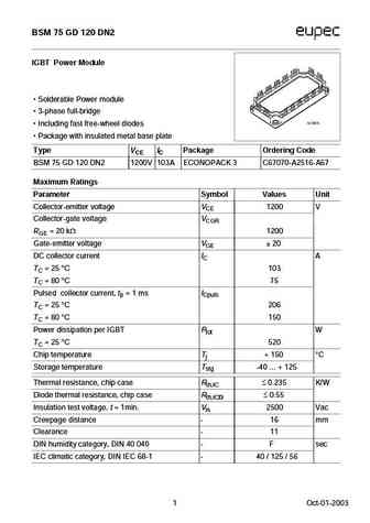
BSM 75 GD 120 DN2 IGBT Power Module Solderable Power module 3-phase full-bridge Including fast free-wheel diodes Package with insulated metal base plate Type VCE IC Package Ordering Code BSM 75 GD 120 DN2 1200V 103A ECONOPACK 3 C67070-A2516-A67 Maximum Ratings Parameter Symbol Values Unit Collector-emitter voltage VCE 1200 V Collector-gate voltage VCGR RGE = 20 k
bsm75gd120dlc.pdf
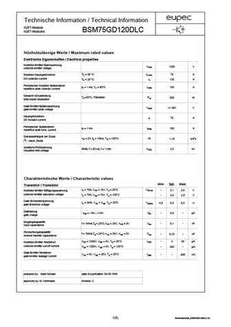
Technische Information / Technical Information IGBT-Module BSM75GD120DLC IGBT-Modules H chstzul ssige Werte / Maximum rated values Elektrische Eigenschaften / Electrical properties Kollektor-Emitter-Sperrspannung VCES 1200 V collector-emitter voltage TC = 80 C IC,nom. 75 A Kollektor-Dauergleichstrom DC-collector current TC = 25 C IC 125 A Periodischer Kollektor Spitzenstrom
bsm15gd120dn2.pdf
BSM 15 GD 120 DN2 IGBT Power Module Power module 3-phase full-bridge Including fast free-wheel diodes Package with insulated metal base plate Type VCE IC Package Ordering Code BSM 15 GD 120 DN2 1200V 25A ECONOPACK 2 C67076-A2504-A67 BSM 15 GD120DN2E3224 1200V 25A ECONOPACK 2K C67070-A2504-A67 Maximum Ratings Parameter Symbol Values Unit Collector-emitter voltage VCE 1
bsm10gd120dn2 e3224.pdf
BSM 10 GD 120 DN2 E3224 IGBT Power Module Power module 3-phase full-bridge Including fast free-wheel diodes Package with insulated metal base plate Type VCE IC Package Ordering Code BSM 10 GD 120 DN2 1200V 15A ECONOPACK 2 C67076-A2513-A67 BSM 10 GD120DN2E3224 1200V 15A ECONOPACK 2K C67070-A2513-A67 Maximum Ratings Parameter Symbol Values Unit Collector-emitter voltage
bsm35gd120dlc e3224.pdf
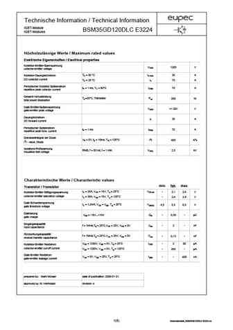
Technische Information / Technical Information IGBT-Module BSM35GD120DLC E3224 IGBT-Modules H chstzul ssige Werte / Maximum rated values Elektrische Eigenschaften / Electrical properties Kollektor-Emitter-Sperrspannung VCES 1200 V collector-emitter voltage TC = 80 C IC,nom. 35 A Kollektor-Dauergleichstrom DC-collector current TC = 25 C IC 70 A Periodischer Kollektor Spitzens
bsm25gd120dn2.pdf
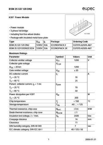
BSM 25 GD 120 DN2 IGBT Power Module Power module 3-phase full-bridge Including fast free-wheel diodes Package with insulated metal base plate Type VCE IC Package Ordering Code BSM 25 GD 120 DN2 1200V 35A ECONOPACK 2 C67076-A2505-A67 BSM 25 GD120DN2E3224 1200V 35A ECONOPACK 2K C67070-A2505-A67 Maximum Ratings Parameter Symbol Values Unit Collector-emitter voltage VCE 1
bsm50gd120dlc.pdf
Technische Information / Technical Information IGBT-Module BSM50GD120DLC IGBT-Modules H chstzul ssige Werte / Maximum rated values Elektrische Eigenschaften / Electrical properties Kollektor-Emitter-Sperrspannung VCES 1200 V collector-emitter voltage TC = 80 C IC,nom. 50 A Kollektor-Dauergleichstrom DC-collector current TC = 25 C IC 85 A Periodischer Kollektor Spitzenstrom
bsm50gd120dn2g.pdf
BSM 50 GD 120 DN2G IGBT Power Module Power module 3-phase full-bridge Including fast free-wheel diodes Package with insulated metal base plate Type VCE IC Package Ordering Code BSM 50 GD 120 DN2G 1200V 78A ECONOPACK 3 C67070-A2521-A67 Maximum Ratings Parameter Symbol Values Unit Collector-emitter voltage VCE 1200 V Collector-gate voltage VCGR RGE = 20 k 1200 Gate

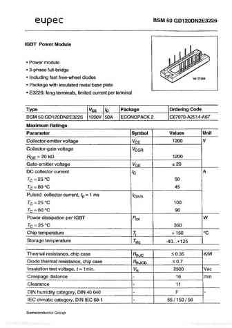
bsm50gd120dn2e3226.pdf
-40...+125 2006-02-01 2006-02-01 2006-02-01 2006-02-01 2006-02-01 2006-02-01 2006-02-01 2006-02-01 BSM 50 GD 120 DN2 E3226 Geh usema e / Schaltbild Package outline / Circuit diagramm 9 2006-02-01 Nutzungsbedingungen Die in diesem Produktdatenblatt enthaltenen Daten sind ausschlie lich f r technisch geschultes Fachpersonal bestimmt. Die Beurteilung der Geeignetheit
bsm25gd120dn2 e3224.pdf
BSM 25 GD 120 DN2 E3224 IGBT Power Module Power module 3-phase full-bridge Including fast free-wheel diodes Package with insulated metal base plate Type VCE IC Package Ordering Code BSM 25 GD 120 DN2 1200V 35A ECONOPACK 2 C67076-A2505-A67 BSM 25 GD120DN2E3224 1200V 35A ECONOPACK 2K C67070-A2505-A67 Maximum Ratings Parameter Symbol Values Unit Collector-emitter voltage
nce25gd135t.pdf
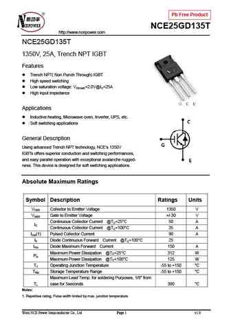
Pb Free Product NCE25GD135T http //www.ncepower.com NCE25GD135T 1350V, 25A, Trench NPT IGBT Features Trench NPT( Non Punch Through) IGBT High speed switching Low saturation voltage VCE(sat)=2.0V@IC=25A High input impedance Applications Inductive heating, Microwave oven, Inverter, UPS, etc. Soft switching applications General Description Using advanced Tre
semix353gd126hdc.pdf
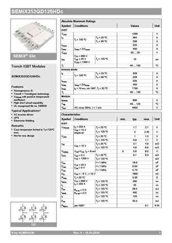
SEMiX353GD126HDc Absolute Maximum Ratings Symbol Conditions Values Unit IGBT VCES 1200 V IC Tc =25 C 364 A Tj = 150 C Tc =80 C 256 A ICnom 225 A ICRM ICRM = 2xICnom 450 A VGES -20 ... 20 V VCC = 600 V SEMiX 33c tpsc VGE 20 V Tj = 125 C 10 s VCES 1200 V Tj -40 ... 150 C Trench IGBT Modules Inverse diode IF Tc =25 C 329 A Tj = 150 C SEMiX353GD126HDc Tc
skim429gd17e4hd.pdf
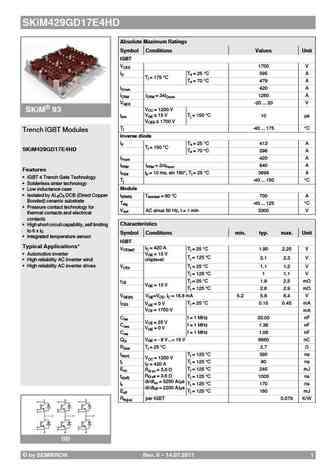
SKiM429GD17E4HD Absolute Maximum Ratings Symbol Conditions Values Unit IGBT VCES 1700 V IC Ts =25 C 595 A Tj = 175 C Ts =70 C 479 A ICnom 420 A ICRM ICRM = 3xICnom 1260 A VGES -20 ... 20 V VCC = 1200 V SKiM 93 tpsc VGE 15 V Tj =150 C 10 s VCES 1700 V Tj -40 ... 175 C Trench IGBT Modules Inverse diode IF Ts =25 C 413 A Tj = 150 C SKiM429GD17E4HD Ts =70
semix71gd12e4s.pdf
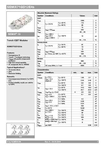
SEMiX71GD12E4s Absolute Maximum Ratings Symbol Conditions Values Unit IGBT VCES 1200 V IC Tc =25 C 115 A Tj = 175 C Tc =80 C 88 A ICnom 75 A ICRM ICRM = 3xICnom 225 A VGES -20 ... 20 V VCC = 800 V SEMiX 13 tpsc VGE 20 V Tj = 150 C 10 s VCES 1200 V Tj -40 ... 175 C Trench IGBT Modules Inverse diode IF Tc =25 C 97 A Tj = 175 C SEMiX71GD12E4s Tc =80 C
semix653gd176hdc.pdf

SEMiX653GD176HDc Absolute Maximum Ratings Symbol Conditions Values Unit IGBT VCES 1700 V IC Tc =25 C 619 A Tj = 150 C Tc =80 C 438 A ICnom 450 A ICRM ICRM = 2xICnom 900 A VGES -20 ... 20 V VCC = 1000 V SEMiX 33c tpsc VGE 20 V Tj = 125 C 10 s VCES 1700 V Tj -55 ... 150 C Trench IGBT Modules Inverse diode IF Tc =25 C 545 A Tj = 150 C SEMiX653GD176HDc T
semix151gd12e4s.pdf

SEMiX151GD12E4s Absolute Maximum Ratings Symbol Conditions Values Unit IGBT VCES 1200 V IC Tc =25 C 232 A Tj = 175 C Tc =80 C 179 A ICnom 150 A ICRM ICRM = 3xICnom 450 A VGES -20 ... 20 V VCC = 800 V SEMiX 13 tpsc VGE 20 V Tj = 150 C 10 s VCES 1200 V Tj -40 ... 175 C Trench IGBT Modules Inverse diode IF Tc =25 C 189 A Tj = 175 C SEMiX151GD12E4s Tc =8
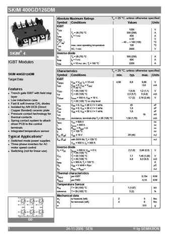

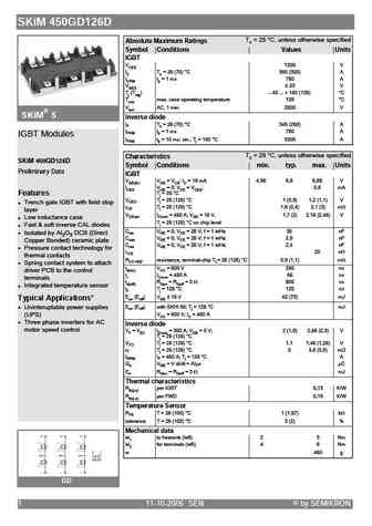
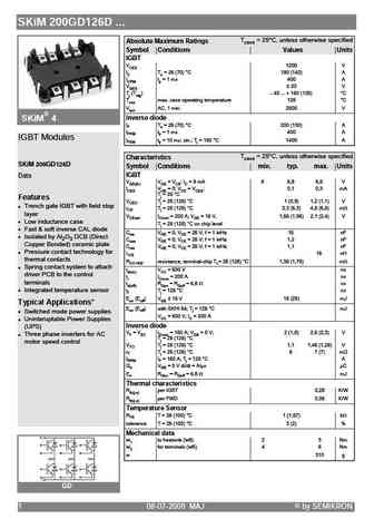
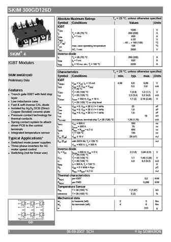
skim400gd126dlm.pdf
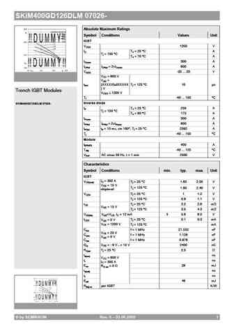
SKiM400GD126DLM 07026- Absolute Maximum Ratings Symbol Conditions Values Unit IGBT VCES 1200 V IC Ts =25 C A Tj = 150 C Ts =70 C A ICnom 300 A ICRM ICRM = 2xICnom 600 A VGES -20 ... 20 V VCC = 600 V VGE = tpsc (XXXXXfailXXXXX Tj = 125 C 10 s ) V Trench IGBT Modules VCES 1200 V Tj -40 ... 150 C Inverse diode SKiM400GD126DLM 07026- IF Ts =25 C 258 A Tj = 150
semix453gd12e4c.pdf
SEMiX453GD12E4c Absolute Maximum Ratings Symbol Conditions Values Unit IGBT VCES 1200 V IC Tc =25 C 683 A Tj = 175 C Tc =80 C 526 A ICnom 450 A ICRM ICRM = 3xICnom 1350 A VGES -20 ... 20 V VCC = 800 V SEMiX 33c tpsc VGE 20 V Tj = 150 C 10 s VCES 1200 V Tj -40 ... 175 C Trench IGBT Modules Inverse diode IF Tc =25 C 544 A Tj = 175 C SEMiX453GD12E4c Tc
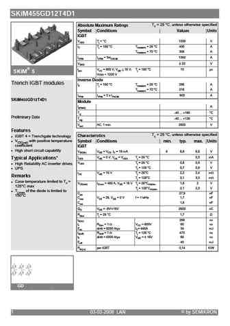
skim459gd12e4.pdf
SKiM459GD12E4 Absolute Maximum Ratings Symbol Conditions Values Unit IGBT VCES 1200 V IC Ts =25 C 554 A Tj = 175 C Ts =70 C 450 A ICnom 450 A ICRM ICRM = 3xICnom 1350 A VGES -20 ... 20 V VCC = 800 V SKiM 93 tpsc VGE 15 V Tj =150 C 10 s VCES 1200 V Tj -40 ... 175 C Trench IGBT Modules Inverse diode IF Ts =25 C 438 A Tj = 175 C SKiM459GD12E4 Ts =70 C 3
semix353gd176hdc.pdf
SEMiX353GD176HDc Absolute Maximum Ratings Symbol Conditions Values Unit IGBT VCES 1700 V IC Tc =25 C 353 A Tj = 150 C Tc =80 C 251 A ICnom 225 A ICRM ICRM = 2xICnom 450 A VGES -20 ... 20 V VCC = 1000 V SEMiX 33c tpsc VGE 20 V Tj = 125 C 10 s VCES 1700 V Tj -55 ... 150 C Trench IGBT Modules Inverse diode IF Tc =25 C 428 A Tj = 150 C SEMiX353GD176HDc T

semix703gd126hdc.pdf

SEMiX703GD126HDc Absolute Maximum Ratings Symbol Conditions Values Unit IGBT VCES 1200 V IC Tc =25 C 642 A Tj = 150 C Tc =80 C 449 A ICnom 450 A ICRM ICRM = 2xICnom 900 A VGES -20 ... 20 V VCC = 600 V SEMiX 33c tpsc VGE 20 V Tj = 125 C 10 s VCES 1200 V Tj -40 ... 150 C Trench IGBT Modules Inverse diode IF Tc =25 C 561 A Tj = 150 C SEMiX703GD126HDc Tc
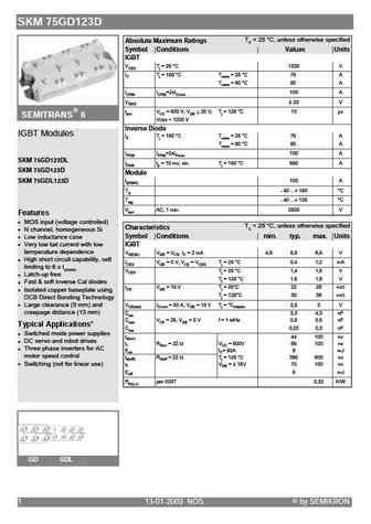
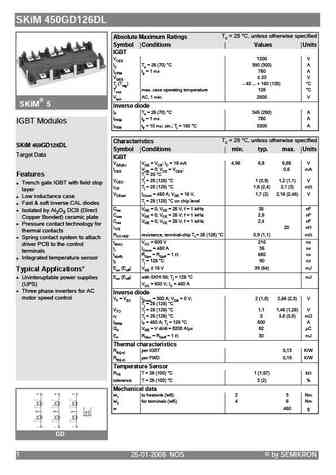
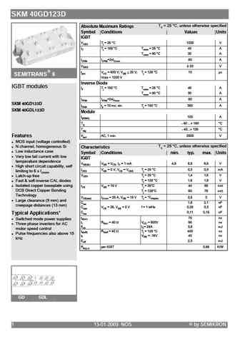
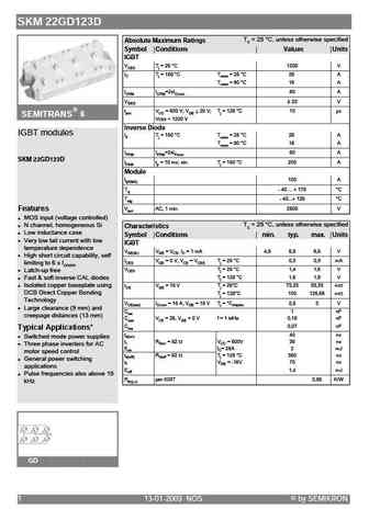
skm75gd124d.pdf
SEMITRANS M Absolute Maximum Ratings Values Low Loss IGBT Modules Symbol Conditions 1) Units VCES 1200 V VCGR RGE = 20 k 1200 V SKM 75 GD 124 D IC Tcase = 25/60 C 90 / 75 A ICM Tcase = 25/60 C; tp = 1 ms 180 / 150 A VGES 20 V Ptot per IGBT, Tcase = 25 C 390 W Tj, (Tstg) 40 ... +150 (125) C Visol AC, 1 min. 2500 V humidity DIN 40 040 Class F climate DIN IEC 68 T
semix303gd12e4c.pdf

SEMiX303GD12E4c Absolute Maximum Ratings Symbol Conditions Values Unit IGBT VCES 1200 V IC Tc =25 C 466 A Tj = 175 C Tc =80 C 359 A ICnom 300 A ICRM ICRM = 3xICnom 900 A VGES -20 ... 20 V VCC = 800 V SEMiX 33c tpsc VGE 20 V Tj = 150 C 10 s VCES 1200 V Tj -40 ... 175 C Trench IGBT Modules Inverse diode IF Tc =25 C 338 A Tj = 175 C SEMiX303GD12E4c Tc =
semix151gd126hds.pdf

SEMiX151GD126HDs Absolute Maximum Ratings Symbol Conditions Values Unit IGBT VCES 1200 V IC Tc =25 C 168 A Tj = 150 C Tc =80 C 119 A ICnom 100 A ICRM ICRM = 2xICnom 200 A VGES -20 ... 20 V VCC = 600 V SEMiX 13 tpsc VGE 20 V Tj = 125 C 10 s VCES 1200 V Tj -40 ... 150 C Trench IGBT Modules Inverse diode IF Tc =25 C 152 A Tj = 150 C SEMiX151GD126HDs Tc
semix251gd126hds.pdf
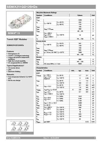
SEMiX251GD126HDs Absolute Maximum Ratings Symbol Conditions Values Unit IGBT VCES 1200 V IC Tc =25 C 242 A Tj = 150 C Tc =80 C 170 A ICnom 150 A ICRM ICRM = 2xICnom 300 A VGES -20 ... 20 V VCC = 600 V SEMiX 13 tpsc VGE 20 V Tj = 125 C 10 s VCES 1200 V Tj -40 ... 150 C Trench IGBT Modules Inverse diode IF Tc =25 C 207 A Tj = 150 C SEMiX251GD126HDs Tc
semix151gd12vs.pdf
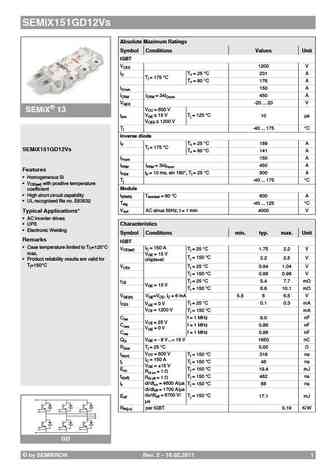
SEMiX151GD12Vs Absolute Maximum Ratings Symbol Conditions Values Unit IGBT VCES 1200 V IC Tc =25 C 231 A Tj = 175 C Tc =80 C 176 A ICnom 150 A ICRM ICRM = 3xICnom 450 A VGES -20 ... 20 V VCC = 600 V SEMiX 13 tpsc VGE 15 V Tj =125 C 10 s VCES 1200 V Tj -40 ... 175 C Inverse diode IF Tc =25 C 189 A Tj = 175 C SEMiX151GD12Vs Tc =80 C 141 A IFnom 150 A
semix453gd12vc.pdf
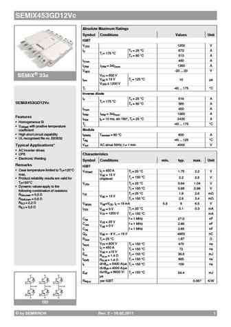
SEMiX453GD12Vc Absolute Maximum Ratings Symbol Conditions Values Unit IGBT VCES 1200 V IC Tc =25 C 673 A Tj = 175 C Tc =80 C 513 A ICnom 450 A ICRM ICRM = 3xICnom 1350 A VGES -20 ... 20 V VCC = 600 V SEMiX 33c tpsc VGE 15 V Tj =125 C 10 s VCES 1200 V Tj -40 ... 175 C Inverse diode IF Tc =25 C 516 A Tj = 175 C SEMiX453GD12Vc Tc =80 C 385 A IFnom 450 A

semix453gd176hdc.pdf

SEMiX453GD176HDc Absolute Maximum Ratings Symbol Conditions Values Unit IGBT VCES 1700 V IC Tc =25 C 444 A Tj = 150 C Tc =80 C 315 A ICnom 300 A ICRM ICRM = 2xICnom 600 A VGES -20 ... 20 V VCC = 1000 V SEMiX 33c tpsc VGE 20 V Tj = 125 C 10 s VCES 1700 V Tj -55 ... 150 C Trench IGBT Modules Inverse diode IF Tc =25 C 545 A Tj = 150 C SEMiX453GD176HDc T
semix101gd12vs.pdf

SEMiX101GD12Vs Absolute Maximum Ratings Symbol Conditions Values Unit IGBT VCES 1200 V IC Tc =25 C 159 A Tj = 175 C Tc =80 C 121 A ICnom 100 A ICRM ICRM = 3xICnom 300 A VGES -20 ... 20 V VCC = 600 V SEMiX 13 tpsc VGE 15 V Tj =125 C 10 s VCES 1200 V Tj -40 ... 175 C Inverse diode IF Tc =25 C 121 A Tj = 175 C SEMiX101GD12Vs Tc =80 C 91 A IFnom 100 A I
semix223gd12e4c.pdf

SEMiX223GD12E4c Absolute Maximum Ratings Symbol Conditions Values Unit IGBT VCES 1200 V IC Tc =25 C 333 A Tj = 175 C Tc =80 C 256 A ICnom 225 A ICRM ICRM = 3xICnom 675 A VGES -20 ... 20 V VCC = 800 V SEMiX 33c tpsc VGE 20 V Tj = 150 C 10 s VCES 1200 V Tj -40 ... 175 C Trench IGBT Modules Inverse diode IF Tc =25 C 270 A Tj = 175 C SEMiX223GD12E4c Tc =
semix101gd126hds.pdf

SEMiX101GD126HDs Absolute Maximum Ratings Symbol Conditions Values Unit IGBT VCES 1200 V IC Tc =25 C 129 A Tj = 150 C Tc =80 C 91 A ICnom 75 A ICRM ICRM = 2xICnom 150 A VGES -20 ... 20 V VCC = 600 V SEMiX 13 tpsc VGE 20 V Tj = 125 C 10 s VCES 1200 V Tj -40 ... 150 C Trench IGBT Modules Inverse diode IF Tc =25 C 117 A Tj = 150 C SEMiX101GD126HDs Tc =8
semix503gd126hdc.pdf
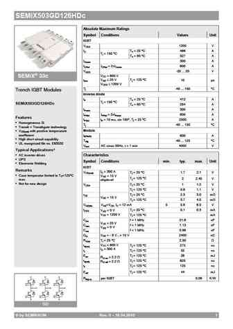
SEMiX503GD126HDc Absolute Maximum Ratings Symbol Conditions Values Unit IGBT VCES 1200 V IC Tc =25 C 466 A Tj = 150 C Tc =80 C 327 A ICnom 300 A ICRM ICRM = 2xICnom 600 A VGES -20 ... 20 V VCC = 600 V SEMiX 33c tpsc VGE 20 V Tj = 125 C 10 s VCES 1200 V Tj -40 ... 150 C Trench IGBT Modules Inverse diode IF Tc =25 C 412 A Tj = 150 C SEMiX503GD126HDc Tc
semix223gd12vc.pdf

SEMiX223GD12Vc Absolute Maximum Ratings Symbol Conditions Values Unit IGBT VCES 1200 V IC Tc =25 C 323 A Tj = 175 C Tc =80 C 246 A ICnom 225 A ICRM ICRM = 3xICnom 675 A VGES -20 ... 20 V VCC = 600 V SEMiX 33c tpsc VGE 15 V Tj =125 C 10 s VCES 1200 V Tj -40 ... 175 C Inverse diode IF Tc =25 C 263 A Tj = 175 C SEMiX223GD12Vc Tc =80 C 197 A IFnom 225 A
semix101gd12e4s.pdf

SEMiX101GD12E4s Absolute Maximum Ratings Symbol Conditions Values Unit IGBT VCES 1200 V IC Tc =25 C 160 A Tj = 175 C Tc =80 C 123 A ICnom 100 A ICRM ICRM = 3xICnom 300 A VGES -20 ... 20 V VCC = 800 V SEMiX 13 tpsc VGE 20 V Tj = 150 C 10 s VCES 1200 V Tj -40 ... 175 C Trench IGBT Modules Inverse diode IF Tc =25 C 121 A Tj = 175 C SEMiX101GD12E4s Tc =8
semix303gd12vc.pdf

SEMiX303GD12Vc Absolute Maximum Ratings Symbol Conditions Values Unit IGBT VCES 1200 V IC Tc =25 C 448 A Tj = 175 C Tc =80 C 342 A ICnom 300 A ICRM ICRM = 3xICnom 900 A VGES -20 ... 20 V VCC = 600 V SEMiX 33c tpsc VGE 15 V Tj =125 C 10 s VCES 1200 V Tj -40 ... 175 C Inverse diode IF Tc =25 C 327 A Tj = 175 C SEMiX303GD12Vc Tc =80 C 244 A IFnom 300 A
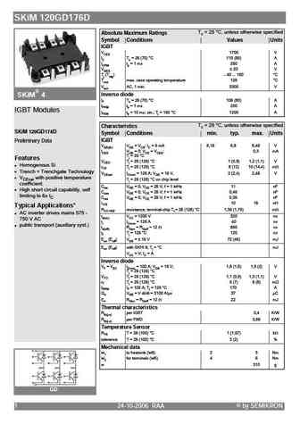
skim306gd12e4.pdf
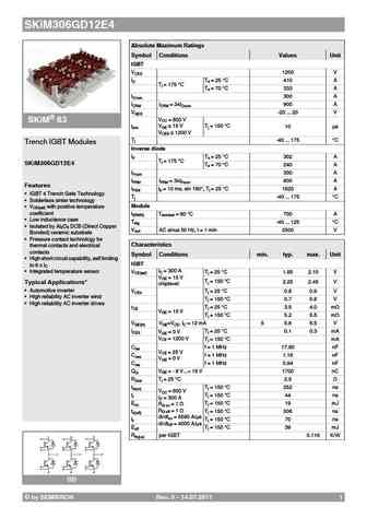
SKiM306GD12E4 Absolute Maximum Ratings Symbol Conditions Values Unit IGBT VCES 1200 V IC Ts =25 C 410 A Tj = 175 C Ts =70 C 333 A ICnom 300 A ICRM ICRM = 3xICnom 900 A VGES -20 ... 20 V VCC = 800 V SKiM 63 tpsc VGE 15 V Tj =150 C 10 s VCES 1200 V Tj -40 ... 175 C Trench IGBT Modules Inverse diode IF Ts =25 C 302 A Tj = 175 C SKiM306GD12E4 Ts =70 C 24
lsgc10r080w3 lsgd10r080w3 lsge10r080w3.pdf
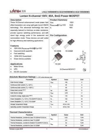
LSGC10R080W3/LSGD10R080W3/LSGE10R080W3 Lonten N-channel 100V, 80A, 8m Power MOSFET Description Product Summary These N-Channel enhancement mode power field V 100V DSS effect transistors are using split gate trench DMOS RDS(on).max@ VGS=10V 8m technology. This advanced technology has been I 80A D especially tailored to minimize on-state resistance, provide superior switching perform
hgd120n06sl hgi120n06sl.pdf
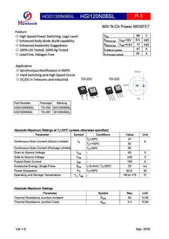
HGD120N06SL , HGI120N06SL P-1 60V N-Ch Power MOSFET Feature 60 V VDS High Speed Power Switching, Logic Level 8.5 RDS(on),typ VGS=10V m Enhanced Body diode dv/dt capability 12 RDS(on),typ VGS=4.5V m Enhanced Avalanche Ruggedness 47 A ID (Sillicon Limited) 100% UIS Tested, 100% Rg Tested 35 A ID (Package Limited) Lead Free, Halogen Free Application
hgd170n10a hgi170n10a.pdf
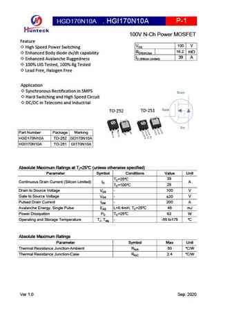
HGD170N10A , P-1 HGI170N10A 100V N-Ch Power MOSFET Feature 100 V VDS High Speed Power Switching 16.2 RDS(on),typ mW Enhanced Body diode dv/dt capability 39 A ID (Sillicon Limited) Enhanced Avalanche Ruggedness 100% UIS Tested, 100% Rg Tested Lead Free, Halogen Free Application Synchronous Rectification in SMPS Drain Hard Switching and High Speed Cir
hgd1k2n20ml hgi1k2n20ml.pdf
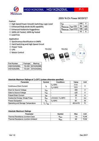
HGD1K2N20ML , HGI1K2N20ML P-1 200V N-Ch Power MOSFET Feature 200 V VDS High Speed Power Smooth Switching, Logic Level 95 RDS(on),typ VGS=10V m Enhanced Body diode dv/dt capability 106 RDS(on),typ VGS=4.5V m Enhanced Avalanche Ruggedness 18 A ID 100% UIS Tested, 100% Rg Tested Lead Free Application Synchronous Rectification in SMPS Hard Switchi
hgi130n12sl hgd130n12sl.pdf
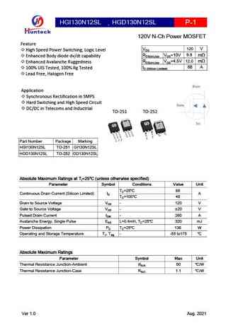
HGI130N12SL HGD130N12SL , P-1 120V N-Ch Power MOSFET Feature 120 V VDS High Speed Power Switching, Logic Level 9.8 RDS(on),typ VGS=10V mW Enhanced Body diode dv/dt capability 12.0 RDS(on),typ VGS=4.5V mW Enhanced Avalanche Ruggedness 68 A ID (Sillicon Limited) 100% UIS Tested, 100% Rg Tested Lead Free, Halogen Free Drain Application Synchronous
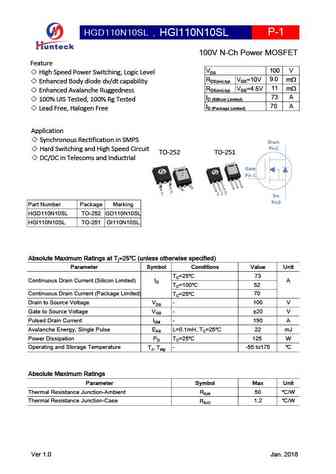
hgd110n08al hgi110n08al.pdf
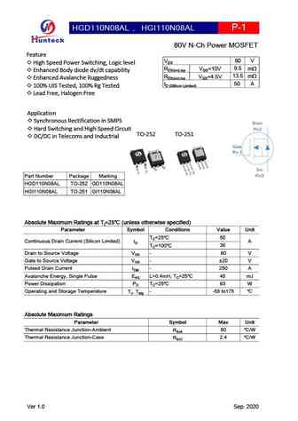
HGD110N08AL , HGI110N08AL P-1 80V N-Ch Power MOSFET Feature 80 V VDS High Speed Power Switching, Logic level 9.5 RDS(on),typ VGS=10V mW Enhanced Body diode dv/dt capability 13.5 RDS(on),typ VGS=4.5V mW Enhanced Avalanche Ruggedness 50 A ID (Sillicon Limited) 100% UIS Tested, 100% Rg Tested Lead Free, Halogen Free Application Synchronous Rectification in
hgd100n12sl.pdf

HGD100N12SL P-1 120V N-Ch Power MOSFET Feature 120 V VDS High Speed Power Switching,Logic level 7.8 RDS(on),typ VGS=10V mW Enhanced Body diode dv/dt capability 8.6 RDS(on),typ VGS=4.5V mW Enhanced Avalanche Ruggedness 102 A ID (Sillicon Limited) 100% UIS Tested, 100% Rg Tested 70 A ID (Package Limited) Lead Free Application Synchronous Rectification in
hgd170n10al hgi170n10al.pdf
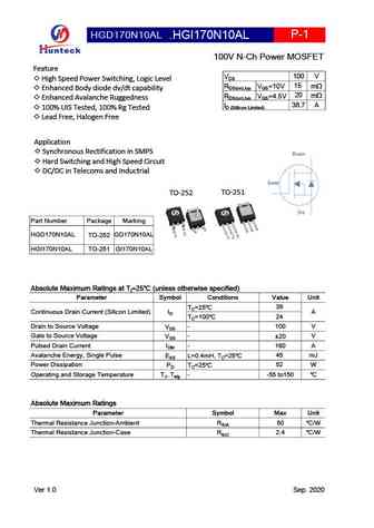
HGD170N10AL , P-1 HGI170N10AL 100V N-Ch Power MOSFET Feature 100 V VDS High Speed Power Switching, Logic Level 15 RDS(on),typ VGS=10V mW Enhanced Body diode dv/dt capability 20 RDS(on),typ VGS=4.5V mW Enhanced Avalanche Ruggedness 38.7 A ID (Sillicon Limited) 100% UIS Tested, 100% Rg Tested Lead Free, Halogen Free Application Synchronous Rectification i
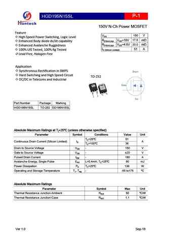
hgd195n15s.pdf
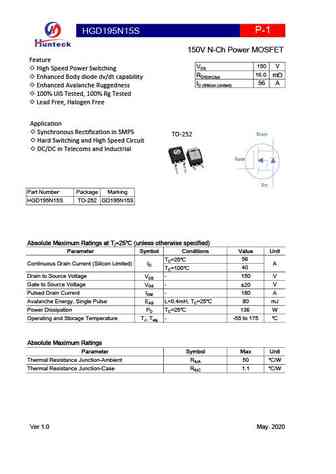
HGD195N15S P-1 150V N-Ch Power MOSFET Feature 150 V VDS High Speed Power Switching 16.0 RDS(on),typ mW Enhanced Body diode dv/dt capability 56 A ID (Sillicon Limited) Enhanced Avalanche Ruggedness 100% UIS Tested, 100% Rg Tested Lead Free, Halogen Free Application Synchronous Rectification in SMPS Drain TO-252 Hard Switching and High Speed Circuit
hgd110n08a hgi110n08a.pdf
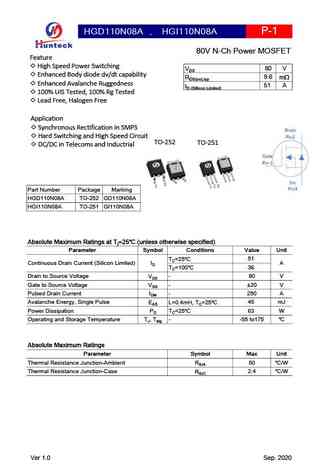
HGD110N08A , HGI110N08A P-1 80V N-Ch Power MOSFET Feature High Speed Power Switching 80 V VDS Enhanced Body diode dv/dt capability 9.6 RDS(on),typ mW Enhanced Avalanche Ruggedness 51 A ID (Sillicon Limited) 100% UIS Tested, 100% Rg Tested Lead Free, Halogen Free Application Synchronous Rectification in SMPS Drain Hard Switching and High Speed Circuit
hgd190n15sl.pdf
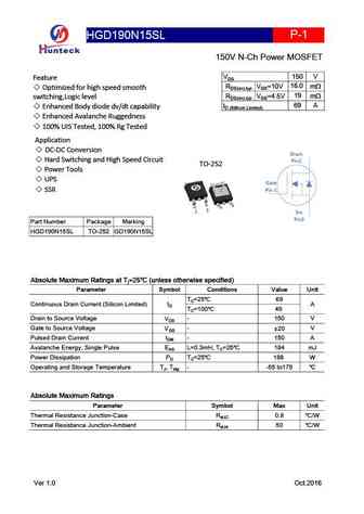
HGD190N15SL P-1 150V N-Ch Power MOSFET 150 V VDS Feature 16.0 RDS(on),typ VGS=10V m Optimized for high speed smooth 19 RDS(on),typ VGS=4.5V m switching,Logic level 69 A ID (Sillicon Limited) Enhanced Body diode dv/dt capability Enhanced Avalanche Ruggedness 100% UIS Tested, 100% Rg Tested Application DC-DC Conversion Drain Hard Switching and H
hgd155n15s.pdf
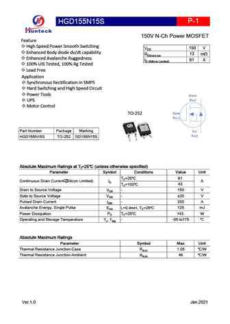
P-1 HGD155N15S 150V N-Ch Power MOSFET Feature High Speed Power Smooth Switching 150 V VDS Enhanced Body diode dv/dt capability 13 RDS(on),typ mW Enhanced Avalanche Ruggedness 61 A ID (Sillicon Limited) 100% UIS Tested, 100% Rg Tested Lead Free Application Synchronous Rectification in SMPS Hard Switching and High Speed Circuit Power Tools Drain
hgi120n10al hgd120n10al.pdf
, HGI120N10AL HGD120N10AL P-1 100V N-Ch Power MOSFET Feature 100 V VDS High Speed Power Switching, Logic Level 11.4 RDS(on),typ VGS=10V mW Enhanced Body diode dv/dt capability 15.5 RDS(on),typ VGS=4.5V mW Enhanced Avalanche Ruggedness 60 A ID (Silicon limited) 100% UIS Tested, 100% Rg Tested Lead Free, Halogen Free Application Drain Synchronous Rectific
hgd195n15sl.pdf
P-1 HGD195N15SL 150V N-Ch Power MOSFET Feature 150 V VDS High Speed Power Switching, Logic Level 17.5 RDS(on),typ VGS=10V mW Enhanced Body diode dv/dt capability 20.0 RDS(on),typ VGS=4.5V mW Enhanced Avalanche Ruggedness 51 A ID (Sillicon Limited) 100% UIS Tested, 100% Rg Tested Lead Free, Halogen Free Application Synchronous Rectification in SMPS Drai
hgd100n12s.pdf
HGD100N12S P-1 120V N-Ch Power MOSFET Feature 120 V VDS High Speed Power Switching TO-252 8.6 RDS(on),typ m Enhanced Body diode dv/dt capability 102 A ID (Sillicon Limited) Enhanced Avalanche Ruggedness 70 A ID (Package Limited) 100% UIS Tested, 100% Rg Tested Lead Free Application Synchronous Rectification in SMPS Hard Switching and High Speed C
hgi120n10a hgd120n10a.pdf
, HGI120N10A HGD120N10A P-1 100V N-Ch Power MOSFET Feature 100 V VDS High Speed Power Switching 12.0 RDS(on),typ mW Enhanced Body diode dv/dt capability 59 A ID Enhanced Avalanche Ruggedness 100% UIS Tested, 100% Rg Tested Lead Free, Halogen Free Application Synchronous Rectification in SMPS Drain Hard Switching and High Speed Circuit DC/DC in
gd100hfx65c1s.pdf
GD100HFX65C1S IGBT Module STARPOWER SEMICONDUCTOR IGBT GD100HFX65C1S 650V/100A 2 in one-package General Description STARPOWER IGBT Power Module provides ultra low conduction loss as well as short circuit ruggedness. They are designed for the applications such as general inverters and UPS. Features Low VCE(sat) Trench IGBT technology 6 s short circuit capability
Otros transistores... G50N10 , G60N04 , G66 , G66-3L , G68 , G69 , G80N06 , G96 , IRFB4227 , G22 , G23 , G11 , G16 , G17 , 03N06 , 05N06 , 100N03 .
History: IRFP3415
History: IRFP3415
🌐 : EN ES РУ

Liste
Recientemente añadidas las descripciónes de los transistores:
MOSFET: ASB80R750E | ASB70R380E | ASB65R300E | ASB65R220E | ASB65R120EFD | ASB60R150E | ASA80R900E | ASA80R750E | ASA80R290E | ASA70R950E | ASA70R600E | ASA70R380E | ASA70R240E | ASA65R850E | ASA65R550E | ASA65R350E
Popular searches
2sa750 datasheet | 2sa940 transistor datasheet | 2sb549 | 5n50 mosfet equivalent | a1016 transistor | a1693 transistor | a933 datasheet | c535 transistor