HY1908P Datasheet. Equivalente. Reemplazo. Hoja de especificaciones. Principales características
Número de Parte: HY1908P
Tipo de FET: MOSFET
Polaridad de transistor: N
ESPECIFICACIONES MÁXIMAS
Pdⓘ - Máxima disipación de potencia: 185 W
|Vds|ⓘ - Voltaje máximo drenador-fuente: 80 V
|Vgs|ⓘ - Voltaje máximo fuente-puerta: 25 V
|Id|ⓘ - Corriente continua de drenaje: 90 A
Tjⓘ - Temperatura máxima de unión: 175 °C
CARACTERÍSTICAS ELÉCTRICAS
trⓘ - Tiempo de subida: 42 nS
Cossⓘ - Capacitancia de salida: 389 pF
RDSonⓘ - Resistencia estado encendido drenaje a fuente: 0.009 Ohm
Encapsulados: TO220
Búsqueda de reemplazo de HY1908P MOSFET
- Selecciónⓘ de transistores por parámetros
HY1908P datasheet
hy1908p hy1908m hy1908b hy1908mf hy1908ps hy1908pm.pdf
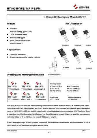
HY1908P/M/B/ MF /PS/PM N-Channel Enhancement Mode MOSFET Feature Pin Description 80V/90A RDS(ON)= 7m (typ.)@VGS = 10V 100% Avalanche Tested Reliable and Rugged Lead- Free Devices Available (RoHS Compliant) TO-220FB-3L TO-220FB-3S TO-263-2L Applications Switching application Power management for inverter systems TO-220MF-3L TO-3PS-3L TO-3PM-
hy1908d hy1908u hy1908s.pdf
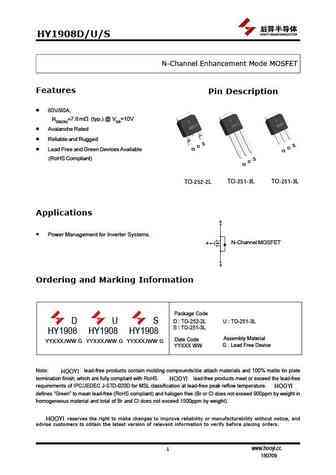
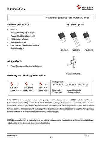
HY1908D/U/S N-Channel Enhancement Mode MOSFET Features Pin Description 80V/90A, 7.8 (typ.) @ VGS=10V RDS(ON)= m Avalanche Rated Reliable and Rugged S S D D G Lead Free and Green Devices Available G (RoHS Compliant) S D G TO-251-3L TO-251-3L TO-252-2L Applications D Power Management for Inverter Systems. G N-Channel MOSFET S Ordering and Marking Informatio
hy1904c2.pdf
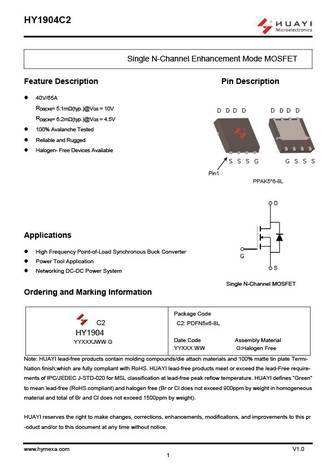
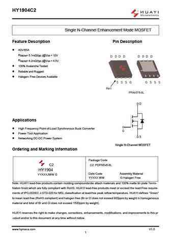
HY1904C2 Single N-Channel Enhancement Mode MOSFET Feature Description Pin Description 40V/65A RDS(ON)= 5.1m (typ.)@VGS = 10V D D D D D D D D RDS(ON)= 6.2m (typ.)@VGS = 4.5V 100% Avalanche Tested Reliable and Rugged Halogen- Free Devices Available S S S G G S S S Pin1 PPAK5*6-8L Applications High Frequency Point-of-Load Synchronous Buck Converter Powe
hy1906c2.pdf
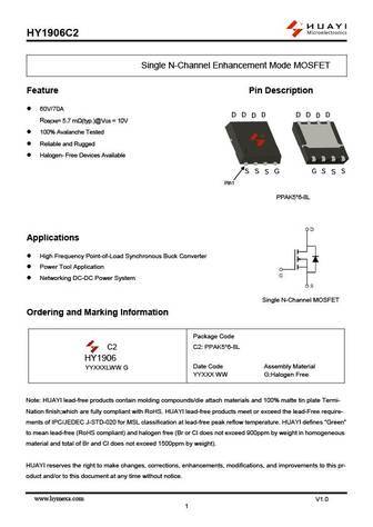
HY1906C2 Single N-Channel Enhancement Mode MOSFET Feature Pin Description 60V/70A D D D D D D D D RDS(ON)= 5.7 m (typ.)@VGS = 10V 100% Avalanche Tested Reliable and Rugged Halogen- Free Devices Available S S S G G S S S Pin1 PPAK5*6-8L Applications High Frequency Point-of-Load Synchronous Buck Converter Power Tool Application Networking DC-DC Powe

Otros transistores... HY1804B, HY1904C2, HY1904D, HY1904U, HY1904V, HY1908D, HY1908U, HY1908S, 5N65, HY1908M, HY1908B, HY1908MF, HY1908PS, HY1908PM, HY1915P, HY1915B, HY1920P
🌐 : EN ES РУ

Liste
Recientemente añadidas las descripciónes de los transistores:
MOSFET: RM50P30DF | CRTT095N12N | CRSS028N10N | CRST030N10N | CRJQ80N65F | ASDM20N20KQ | ASDM20N100Q | ASDM12N65F | ASDM100R750PKQ | ASDM100R160NKQ | ASDM100R090NP | ASDM100R066NQ | ASDM100R045NQ | ASDM100N34KQ | ASDM100N15KQ | FTF30P35D
Popular searches
2sc1740 | c3229 | c2078 transistor | 2sc458 transistors | 2sa992 | 2sa970 | a970 | d2390 transistor