ixgr32n60cd1.pdf Principales características:
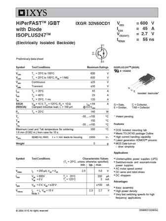
VCES = 600 V HiPerFASTTM IGBT IXGR 32N60CD1 IC25 = 45 A with Diode VCE(SAT) = 2.7 V ISOPLUS247TM tfi(typ) = 55 ns (Electrically Isolated Backside) Preliminary data sheet Symbol Test Conditions Maximum Ratings ISOPLUS 247TM (IXGR) E 153432 VCES TJ = 25 C to 150 C 600 V VCGR TJ = 25 C to 150 C; RGE = 1 M 600 V VGES Continuous 20 V VGEM Transient 30 V G C IC25 TC = 25 C45 A E Isolated backside* IC90 TC = 90 C28 A ICM TC = 25 C, 1 ms 120 A SSOA VGE = 15 V, TVJ = 125 C, RG = 10 ICM = 64 A G = Gate, C = Collector, (RBSOA) Clamped inductive load, L = 100 H @ 0.8 VCES E = Emitter, TAB = Collector PC TC = 25 C 140 W TJ -55 ... +150 C * Patent pending TJM 150 C Features Tstg -55 ... +150 C Maximum Lead and Tab temperature for soldering 300 C DCB Isolated mounting tab 1.6 mm (0.062 in.) from case for 10 s Meets TO-247AD package
Keywords - ALL TRANSISTORS. Principales características
ixgr32n60cd1.pdf Design, MOSFET, Power
ixgr32n60cd1.pdf RoHS Compliant, Service, Triacs, Semiconductor
ixgr32n60cd1.pdf Database, Innovation, IC, Electricity
Parámetros del transistor bipolar y su interrelación.
🌐 : EN ES РУ

Liste
Recientemente añadidas las descripciónes de los transistores:
BJT: ZDT6705 | GA1L4Z | GA1A4M | SBT42 | 2SA200-Y | 2SA200-O | 2SD882-Q | 2SD882-P | 2SD882-E | 2SC945-L | 2SC945-H | 2SC4226-R23 | 2SC3357-F | 2SC3357-E | 2SC3356-R26 | 2SC3356-R24 | 2SC3356-R23 | 2SB772-Q | 2SB772-P | 2SB772-E | 2SA1015-L
Popular searches
irfz44n | irf3205 | irfz44n datasheet | 2n4401 | bc547 transistor | bd139 | 2n4401 datasheet