C101 Equivalente. Reemplazo. Hoja de especificaciones. Principales características
Número de Parte: C101
Material: Si
Polaridad de transistor: PNP
ESPECIFICACIONES MÁXIMAS
Disipación total del dispositivo (Pc): 0.25 W
Tensión colector-base (Vcb): 30 V
Corriente del colector DC máxima (Ic): 0.05 A
Temperatura operativa máxima (Tj): 150 °C
CARACTERÍSTICAS ELÉCTRICAS
Transición de frecuencia (fT): 0.4 MHz
Capacitancia de salida (Cc): 50 pF
Ganancia de corriente contínua (hFE): 9
Encapsulados: TO5
Búsqueda de reemplazo de C101
- Selecciónⓘ de transistores por parámetros
C101 datasheet
0.1. Size:82K sanyo
rc101c.pdf 
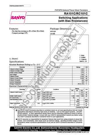
Ordering number EN4775 PNP/NPN Epitaxial Planar Silicon Transistors RA101C/RC101C Switching Applications (with Bias Resistances) Features Package Dimensions On-chip bias resistances (R1=47k , R2=47k ). unit mm Compact package (CP). 2018B [RA101C/RC101C] 0.4 0.16 3 0 to 0.1 1 0.95 2 0.95 1.9 2.9 1 Base 2 Emitter ( ) RA101C 3 Collector SANYO CP Spec
0.2. Size:446K diodes
dmc1017upd.pdf
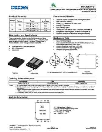
DMC1017UPD COMPLEMENTARY PAIR ENHANCEMENT MODE MOSFET POWERDI 5060-8 Product Summary Features and Benefits Thermally Efficient Package-Cooler Running Applications ID Device V(BR)DSS RDS(ON) TA = +25 C High Conversion Efficiency Low RDS(ON) Minimizes On State Losses 17m @ VGS = 4.5V 9.5A Q1 12V Low Input Capacitance 25m @ VGS = 2.5V 7.8A Fas
0.3. Size:219K infineon
sigc101t170r3e.pdf
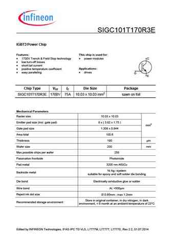
SIGC101T170R3E IGBT3 Power Chip Features This chip is used for 1700V Trench & Field Stop technology power modules C low turn-off losses short tail current Applications positive temperature coefficient drives easy paralleling G E Chip Type VCE IC Die Size Package SIGC101T170R3E 1700V 75A 10.03 x 10.03 mm2 sawn on foil Mechanical Paramete
0.4. Size:126K infineon
sigc101t170r3.pdf

SIGC101T170R3E IGBT3 Power Chip Features This chip is used for 1700V Trench & Field Stop technology power modules C low turn-off losses short tail current Applications positive temperature coefficient drives easy paralleling G E Chip Type VCE IC Die Size Package SIGC101T170R3E 1700V 75A 10.03 x 10.03 mm2 sawn on foil Mechanical Parameters
0.5. Size:401K kec
krc101-krc106.pdf
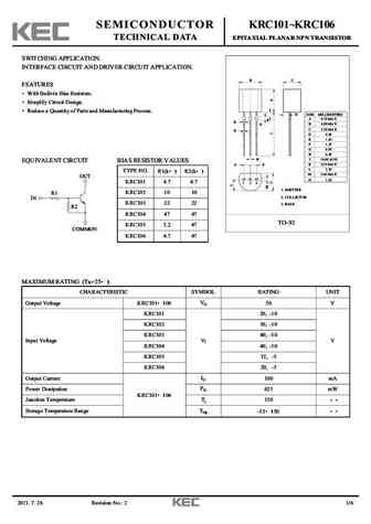
SEMICONDUCTOR KRC101 KRC106 TECHNICAL DATA EPITAXIAL PLANAR NPN TRANSISTOR SWITCHING APPLICATION. INTERFACE CIRCUIT AND DRIVER CIRCUIT APPLICATION. B C FEATURES With Built-in Bias Resistors. Simplify Circuit Design. Reduce a Quantity of Parts and Manufacturing Process. N DIM MILLIMETERS A 4.70 MAX E K B 4.80 MAX G C 3.70 MAX D D 0.45 E 1.00 F 1.27 G 0.85 H 0.45 _
0.6. Size:391K kec
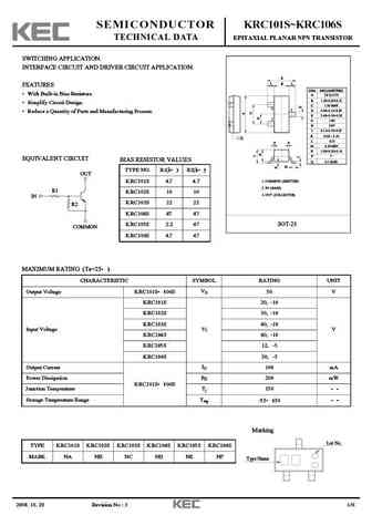
krc101s-krc106s.pdf

SEMICONDUCTOR KRC101S KRC106S TECHNICAL DATA EPITAXIAL PLANAR NPN TRANSISTOR SWITCHING APPLICATION. INTERFACE CIRCUIT AND DRIVER CIRCUIT APPLICATION. E L B L FEATURES DIM MILLIMETERS With Built-in Bias Resistors. _ + A 2.93 0.20 B 1.30+0.20/-0.15 Simplify Circuit Design. C 1.30 MAX 2 3 D 0.40+0.15/-0.05 Reduce a Quantity of Parts and Manufacturing Process. E 2.40+0.30/
0.7. Size:426K kec
krc101m-krc106m.pdf
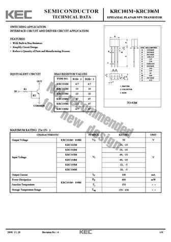
SEMICONDUCTOR KRC101M KRC106M TECHNICAL DATA EPITAXIAL PLANAR NPN TRANSISTOR SWITCHING APPLICATION. INTERFACE CIRCUIT AND DRIVER CIRCUIT APPLICATION. B FEATURES With Built-in Bias Resistors. Simplify Circuit Design. DIM MILLIMETERS O A 3.20 MAX Reduce a Quantity of Parts and Manufacturing Process. H M B 4.30 MAX C 0.55 MAX _ D 2.40 + 0.15 E 1.27 F 2.30 C _ + G 14.
0.8. Size:391K kec
krc101s krc102s krc103s krc104s krc105s krc106s.pdf
SEMICONDUCTOR KRC101S KRC106S TECHNICAL DATA EPITAXIAL PLANAR NPN TRANSISTOR SWITCHING APPLICATION. INTERFACE CIRCUIT AND DRIVER CIRCUIT APPLICATION. E L B L FEATURES DIM MILLIMETERS With Built-in Bias Resistors. _ + A 2.93 0.20 B 1.30+0.20/-0.15 Simplify Circuit Design. C 1.30 MAX 2 3 D 0.40+0.15/-0.05 Reduce a Quantity of Parts and Manufacturing Process. E 2.40+0.30/
0.9. Size:1114K alfa-mos
afc1016.pdf
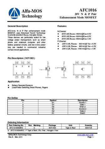
AFC1016 Alfa-MOS 20V N & P Pair Technology Enhancement Mode MOSFET General Description Features AFC1016, N & P Pair enhancement mode N-Channel MOSFET, uses Advanced Trench Technology 20V/0.6A,RDS(ON)= 360m @VGS=4.5V to provide excellent RDS(ON), low gate charge. 20V/0.5A,RDS(ON)= 420m @VGS=2.5V These devices are particularly suited for low 20V/0.4A,RDS(ON)= 560m
0.10. Size:674K cystek
mtc1016s6r.pdf
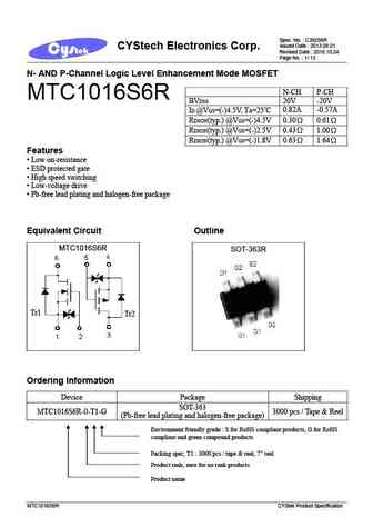
Spec. No. C392S6R Issued Date 2013.08.01 CYStech Electronics Corp. Revised Date 2018.10.24 Page No. 1/ 13 N- AND P-Channel Logic Level Enhancement Mode MOSFET N-CH P-CH MTC1016S6R BVDSS 20V -20V ID @VGS=(-)4.5V, TA=25 C 0.82A -0.57A RDSON(typ.) @VGS=(-)4.5V 0.30 0.61 RDSON(typ.) @VGS=(-)2.5V 0.43 1.00 RDSON(typ.) @VGS=(-)1.8V 0.63 1.64 Features
0.11. Size:282K first silicon
dtc101-dtc108 dtc110-dtc112 dtc114 dtc117 dtc123 dtc124.pdf
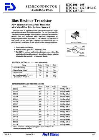
DTC 101 108 SEMICONDUCTOR DTC 110 112 / 114 /117 TECHNICAL DATA DTC 123 / 124 Bias Resistor Transistor NPN Silicon Surface Mount Transistor with Monolithic Bias Resistor Network This new series of digital transistors is designed to replace a single device and its external resistor bias network. The BRT (Bias Resistor 3 Transistor) contains a single transistor with a monolithic bi
0.12. Size:2134K kexin
krc101s-106s.pdf
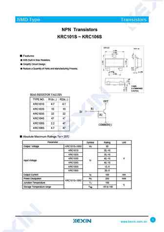
SMD Type Transistors NPN Transistors KRC101S KRC106S SOT-23 Unit mm 2.9+0.1 -0.1 +0.1 0.4-0.1 3 Features With Built-in Bias Resistors. Simplify Circuit Design. 1 2 Reduce a Quantity of Parts and Manufacturing Process. +0.1 +0.05 0.95 -0.1 0.1 -0.01 +0.1 1.9 -0.1 1.IN(B) 2.COMMON(E) 3.OUT(C) BIAS RESISTOR VALUES TYPE NO. R1(k ) R2(k ) OUT KRC101S
0.13. Size:106K diotec
mmbtrc101ss mmbtrc102ss mmbtrc103ss mmbtrc104ss mmbtrc105ss mmbtrc106ss.pdf
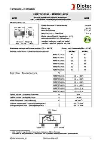
MMBTRC101SS ... MMBTRC106SS MMBTRC101SS ... MMBTRC106SS Surface Mount Bias Resistor Transistors NPN NPN SMD Transistoren mit Eingangsspannungsteiler Version 2011-02-10 Power dissipation Verlustleistung 200 mW 0.1 1.1 2.9 Plastic case SOT-23 0.4 3 Kunststoffgeh use (TO-236) Type Weight approx. Gewicht ca. 0.01 g Code 1 2 Plastic material has UL classification 94V-
0.14. Size:266K syncpower
spc1016.pdf
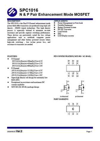
SPC1016 N & P Pair Enhancement Mode MOSFET DESCRIPTION APPLICATIONS Power Management in Note book The SPC1016 is the Dual P-Channel enhancement mode Portable Equipment power field effect transistors are produced using high cell Battery Powered System density , DMOS trench technology. This high density DC/DC Converter process is especially tailored to minimize on-state
0.15. Size:292K syncpower
spc1018.pdf
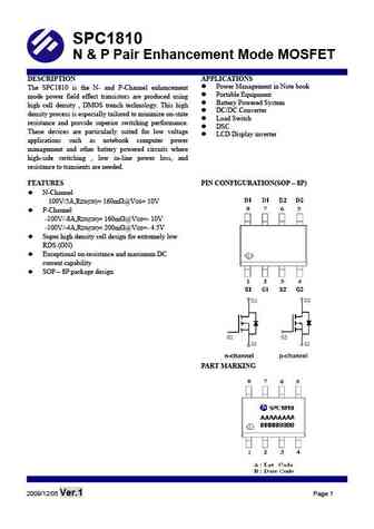
SPC1810 N & P Pair Enhancement Mode MOSFET DESCRIPTION APPLICATIONS Power Management in Note book The SPC1810 is the N- and P-Channel enhancement Portable Equipment mode power field effect transistors are produced using Battery Powered System high cell density , DMOS trench technology. This high DC/DC Converter density process is especially tailored to minimize on-sta
Otros transistores... C066, C066P, C1, C100, C1001, C1002, C1003, C1004, 2N4401, C102, C103, C106, C112, C1-12, C118, C119, C12-28
