2SD261G Datasheet. Specs and Replacement
Type Designator: 2SD261G
Material of Transistor: Si
Polarity: NPN
Absolute Maximum Ratings
Maximum Collector Power Dissipation (Pc): 0.5 W
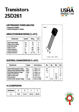
Maximum Collector-Base Voltage |Vcb|: 40 V
Maximum Collector-Emitter Voltage |Vce|: 20 V
Maximum Emitter-Base Voltage |Veb|: 5 V
Maximum Collector Current |Ic max|: 0.5 A
Max. Operating Junction Temperature (Tj): 150 °C
Electrical Characteristics
Transition Frequency (ft): 160 MHz
Forward Current Transfer Ratio (hFE), MIN: 200
Package: TO92
2SD261G Substitution
- BJT ⓘ Cross-Reference Search
2SD261G datasheet
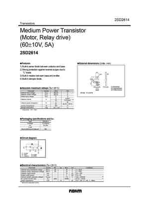
2SD2614 Transistors Medium Power Transistor (Motor, Relay drive) (60 10V, 5A) 2SD2614 Features External dimensions (Units mm) 1) Built-in zener diode between collector and base. 2) Strong protection against reverse surges due to 10.0 4.5 "L" loads. 3.2 2.8 3) Built-in resistor between base and emitter. 4) Built-in damper diode. 1.2 1.3 0.8 0.75 ( ) 2.54 2.54 2.6 (1) ... See More ⇒
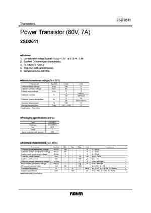
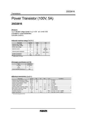
2SD2611 Transistors Power Transistor (80V, 7A) 2SD2611 Features 1) Low saturation voltage, typically VCE(sat) = 0.3V at IC / IB =4 / 0.4A. 2) Excellent DC current gain characteristics. 3) Pc = 30W (Tc = 25 C) 4) Wide SOA (safe operating area). 5) Complements the 2SB1672. Absolute maximum ratings (Ta = 25 C) Parameter Symbol Limits Unit Collector-base voltage VCBO 100 V Collecto... See More ⇒
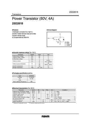
2SD2618 Transistors Power Transistor (80V, 4A) 2SD2618 Features Circuit diagram 1) Darlington connection for a high hFE. C 2) Built-in resistor between base and emitter. 3) Built-in damper doide. 4) Complements the 2SB1676. B R 300 R B Base C Collector E E Emitter Absolute maximum ratings (Ta = 25 C) Parameter Symbol Limits Unit Collector-base voltage VCBO 80 V C... See More ⇒
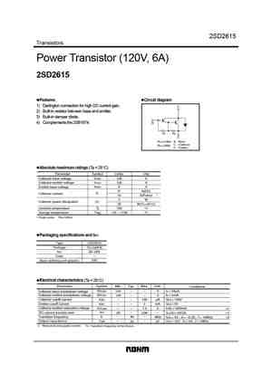
2SD2615 Transistors Power Transistor (120V, 6A) 2SD2615 Features Circuit diagram 1) Darlington connection for high DC current gain. C 2) Built-in resistor between base and emitter. 3) Built-in damper diode. 4) Complements the 2SB1674. B R1 R2 E R1 5.0k B Base C Collector R2 300 E Emitter Absolute maximum ratings (Ta = 25 C) Parameter Symbol Limits Unit Collector... See More ⇒
Detailed specifications: 2SD258, 2SD2589O, 2SD2589P, 2SD2589Y, 2SD259, 2SD26, 2SD260, 2SD261, C1815, 2SD261O, 2SD261R, 2SD261Y, 2SD262, 2SD265, 2SD266, 2SD26A, 2SD26B
Keywords - 2SD261G pdf specs
2SD261G cross reference
2SD261G equivalent finder
2SD261G pdf lookup
2SD261G substitution
2SD261G replacement
