DTC114EEB Specs and Replacement
Type Designator: DTC114EEB
Material of Transistor: Si
Polarity: Pre-Biased-NPN
Built in Bias Resistor R1 = 10 kOhm
Built in Bias Resistor R2 = 10 kOhm
Typical Resistor Ratio R1/R2 = 1
Absolute Maximum Ratings
Maximum Collector Power Dissipation (Pc): 0.15 W
Maximum Collector-Emitter Voltage |Vce|: 50 V
Maximum Emitter-Base Voltage |Veb|: 40 V
Maximum Collector Current |Ic max|: 0.05 A
Max. Operating Junction Temperature (Tj): 150 °C
Electrical Characteristics
Transition Frequency (ft): 250 MHz
Forward Current Transfer Ratio (hFE), MIN: 30
Noise Figure, dB: -
Package: SC-89
EMT3F
SOT416FL
- BJT ⓘ Cross-Reference Search
DTC114EEB datasheet
..1. Size:82K rohm
dtc114eeb.pdf 
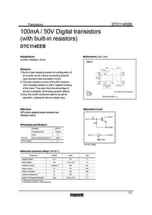
Transistors DTC114EEB 100mA / 50V Digital transistors (with built-in resistors) DTC114EEB Applications Dimensions (Unit mm) Inverter, Interface, Driver EMT3F 1.6 0.7 Features 0.26 1) Built-in bias resistors enable the configuration of (3) an inverter circuit without connecting external input resistors (see equivalent circuit). 2) The bias resistors consist of thin-f... See More ⇒
6.2. Size:55K motorola
pdtc114eef 2.pdf 

DISCRETE SEMICONDUCTORS DATA SHEET M3D425 PDTC114EEF NPN resistor-equipped transistor 1999 May 31 Product specification Supersedes data of 1998 Nov 11 Philips Semiconductors Product specification NPN resistor-equipped transistor PDTC114EEF FEATURES Power dissipation comparable to SOT23 Built-in bias resistors R1 and R2 3 handbook, halfpage (typ. 10 k each) 3 R1 ... See More ⇒
6.4. Size:55K philips
pdtc114eef 2.pdf 

DISCRETE SEMICONDUCTORS DATA SHEET M3D425 PDTC114EEF NPN resistor-equipped transistor 1999 May 31 Product specification Supersedes data of 1998 Nov 11 Philips Semiconductors Product specification NPN resistor-equipped transistor PDTC114EEF FEATURES Power dissipation comparable to SOT23 Built-in bias resistors R1 and R2 3 handbook, halfpage (typ. 10 k each) 3 R1 ... See More ⇒
6.5. Size:152K rohm
dtc114ee.pdf 
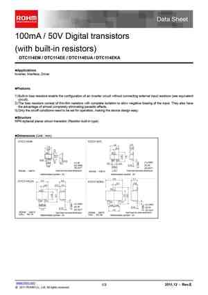
100mA / 50V Digital transistors (with built-in resistors) DTC114EM / DTC114EE / DTC114EUA / DTC114EKA Applications Inverter, Interface, Driver Features 1) Built-in bias resistors enable the configuration of an inverter circuit without connecting external input resistors (see equivalent circuit). 2) The bias resistors consist of thin-film resistors with complete isolation t... See More ⇒
6.6. Size:1522K rohm
dtc114eefra dtc114ekafra dtc114emfha dtc114euafra.pdf 

DTC114E series Datasheet NPN 100mA 50V Digital Transistors (Bias Resistor Built-in Transistors) lOutline l Parameter Value VMT3 EMT3F VCC 50V IC(MAX.) 100mA R1 10k DTC114EM DTC114EEB R2 (SC-105AA) (SC-89) 10k EMT3 UMT3F lFeatures l 1) Built-In Biasing Resistors, R1 = R2 = 10k 2) Built-in bias resistors enable the configuration of ... See More ⇒
6.7. Size:71K rohm
dtc114ee-eua-eka-eca 24 sot416 323 346 23.pdf 
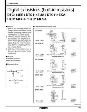
Transistors Digital transistors (built-in resistors) DTC114EE / DTC114EUA / DTC114EKA DTC114ECA / DTC114ESA FFeatures FExternal dimensions (Units mm) 1) Built-in bias resistors enable the configuration of an inverter circuit without connecting external input resistors (see equivalent circuit). 2) The bias resistors consist of thin- film resistors with complete isola- tion to allow n... See More ⇒
6.8. Size:545K diodes
ddtc123ee ddtc143ee ddtc114ee ddtc124ee ddtc144ee ddtc115ee.pdf 
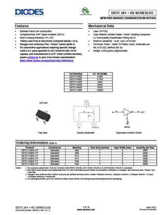
DDTC (R1 = R2 SERIES) EE NPN PRE-BIASED TRANSISTOR IN SOT523 Features Mechanical Data Epitaxial Planar Die Construction Case SOT523 Complementary PNP Types Available (DDTA) Case Material Molded Plastic, Green Molding Compound Built-In Biasing Resistors, R1 = R2 UL Flammability Classification Rating 94V-0 Totally Lead-Free & Fully RoHS Compliant (Notes... See More ⇒
6.9. Size:352K diodes
ddtc114ee.pdf 
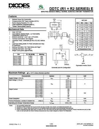
DDTC (R1 = R2 SERIES) E NPN PRE-BIASED SMALL SIGNAL SURFACE MOUNT TRANSISTOR Features A Epitaxial Planar Die Construction SOT-523 Complementary PNP Types Available (DDTA) Built-In Biasing Resistors, R1 = R2 Dim Min Max Typ B C Lead Free/RoHS Compliant (Note 1) TOP VIEW A 0.15 0.30 0.22 "Green" Device (Note 3 and 4) B 0.75 0.85 0.80 C 1.45 1.75 1.60 M... See More ⇒
6.10. Size:144K onsemi
sdtc114eet1g.pdf 
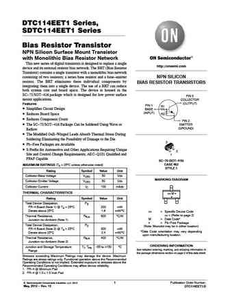
DTC114EET1 Series, SDTC114EET1 Series Bias Resistor Transistor NPN Silicon Surface Mount Transistor with Monolithic Bias Resistor Network This new series of digital transistors is designed to replace a single http //onsemi.com device and its external resistor bias network. The BRT (Bias Resistor Transistor) contains a single transistor with a monolithic bias network consisting of two r... See More ⇒
6.11. Size:92K onsemi
dtc114eet1-series.pdf 
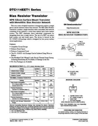
DTC114EET1 Series Bias Resistor Transistor NPN Silicon Surface Mount Transistor with Monolithic Bias Resistor Network This new series of digital transistors is designed to replace a single device and its external resistor bias network. The BRT (Bias Resistor http //onsemi.com Transistor) contains a single transistor with a monolithic bias network consisting of two resistors; a series ba... See More ⇒
6.12. Size:144K onsemi
dtc114eet1g dtc114tet1g dtc114yet1g dtc115eet1g dtc123eet1g.pdf 
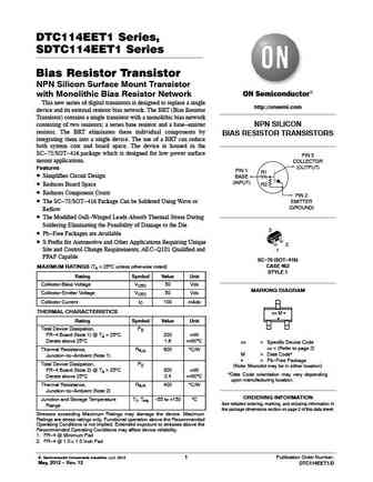
DTC114EET1 Series, SDTC114EET1 Series Bias Resistor Transistor NPN Silicon Surface Mount Transistor with Monolithic Bias Resistor Network This new series of digital transistors is designed to replace a single http //onsemi.com device and its external resistor bias network. The BRT (Bias Resistor Transistor) contains a single transistor with a monolithic bias network consisting of two r... See More ⇒
6.13. Size:116K onsemi
dtc114eet1 8a-m sot416.pdf 
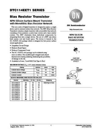
DTC114EET1 SERIES Bias Resistor Transistor NPN Silicon Surface Mount Transistor with Monolithic Bias Resistor Network This new series of digital transistors is designed to replace a single device and its external resistor bias network. The BRT (Bias Resistor http //onsemi.com Transistor) contains a single transistor with a monolithic bias network consisting of two resistors; a series ba... See More ⇒
6.14. Size:420K wietron
dtc114ee.pdf 

DTC114EE Series Bias Resistor Transistor NPN Silicon 3 P b Lead(Pb)-Free COLLECTOR 1 2 3 R1 1 R2 BASE SC-89 (SOT-523F) 2 EMITTER Maximum Ratings (TA=25 C unless otherwise noted) Rating Symbol Value Unit Collector-Emitter Voltage 50 V VCEO VCBO V Collector-Base Voltage 50 mA IC 100 Collector Current-Continuous Thermal Characteristics Characteristics Symbol Max Unit To... See More ⇒
6.15. Size:409K willas
dtc114ee.pdf 

FM120-M WILLAS THRU DTC114EE NPN Digital Transistor FM1200-M 1.0A SURFACE MOUNT SCHOTTKY BARRIER RECTIFIERS -20V- 200V SOD-123 PACKAGE Pb Free Produc Package outline Features Batch process design, excellent power dissipation offers better reverse leakage current and thermal resistance. SOD-123H Low profile surface mounted application in order to optimize board spa... See More ⇒
6.16. Size:435K lrc
ldtc114eet1g.pdf 
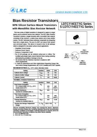
LESHAN RADIO COMPANY, LTD. Bias Resistor Transistors LDTC114EET1G Series NPN Silicon Surface Mount Transistors S-LDTC114EET1G Series with Monolithic Bias Resistor Network This new series of digital transistors is designed to replace a single device and its external resistor bias network. The BRT (Bias Resistor Transistor) contains a single transistor with a monolithic bias network cons... See More ⇒
6.17. Size:1006K kexin
dtc114ee.pdf 

SMD Type Transistors Digital Transistors DTC114EE (KDTC114EE) SOT-523 U nit m m Features +0. 1 1.6 -0. 1 +0.1 1.0 -0.1 Repetitive peak off-state voltages 50V +0.05 0.2 -0.05 0.1+0.01 -0.01 The bias resistors consist of thinfilm resistors with complete isolation 2 1 to allow negative biasing of the input. Only the on/off conditions need to 3 +0.25 be set fo... See More ⇒
6.18. Size:95K chenmko
chdtc114eegp.pdf 
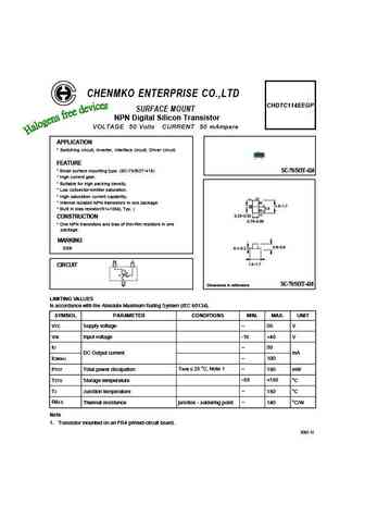
CHENMKO ENTERPRISE CO.,LTD CHDTC114EEGP SURFACE MOUNT NPN Digital Silicon Transistor VOLTAGE 50 Volts CURRENT 50 mAmpere APPLICATION * Switching circuit, Inverter, Interface circuit, Driver circuit. FEATURE * Small surface mounting type. (SC-75/SOT-416) SC-75/SOT-416 * High current gain. * Suitable for high packing density. * Low colloector-emitter saturation. * High saturation cu... See More ⇒
6.19. Size:671K cn shikues
dtc114ee.pdf 

DTC114EE NPN Silicon Epitaxial Planar Digital Transistor Collector Features (Output) With built-in bias resistors R1 Base Simplify circuit design (Input) Reduce a quantity of parts and R2 manufacturing process Emitter (Common) Absolute Maximum Ratings (Ta = 25 ) Parameter Symbol Value Unit Collector Emitter Voltage VCEO 50 V Input Voltage VI - 10 to + ... See More ⇒
Detailed specifications: DTC043EM, DTC043EUB, DTC043ZEB, DTC043ZM, DTC043ZUB, DTC044EEB, DTC044EM, DTC044EUB, 2N3055, DTC114EM, DTC114EUB, DTC114WE, DTC114YEB, DTC114YM, DTC114YUA, DTC114YUB, DTC115EEB
Keywords - DTC114EEB pdf specs
DTC114EEB cross reference
DTC114EEB equivalent finder
DTC114EEB pdf lookup
DTC114EEB substitution
DTC114EEB replacement

