DTA114EMFHA Specs and Replacement
Type Designator: DTA114EMFHA
SMD Transistor Code: 14
Material of Transistor: Si
Polarity: Pre-Biased-PNP
Built in Bias Resistor R1 = 10 kOhm
Built in Bias Resistor R2 = 10 kOhm
Typical Resistor Ratio R1/R2 = 1
Absolute Maximum Ratings
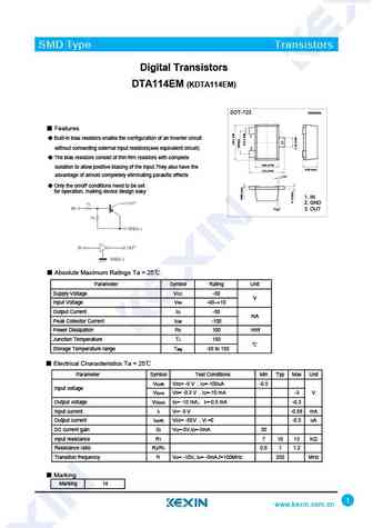
Maximum Collector Power Dissipation (Pc): 0.15 W
Maximum Collector-Emitter Voltage |Vce|: 50 V
Maximum Emitter-Base Voltage |Veb|: 10 V
Maximum Collector Current |Ic max|: 0.05 A
Max. Operating Junction Temperature (Tj): 150 °C
Electrical Characteristics
Transition Frequency (ft): 250 MHz
Forward Current Transfer Ratio (hFE), MIN: 30
Package: SC-105AA
DTA114EMFHA Substitution
- BJT ⓘ Cross-Reference Search
DTA114EMFHA datasheet
dta114eefra dta114ekafra dta114emfha dta114euafra.pdf ![]()
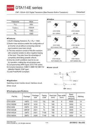
DTA114E series Datasheet PNP -100mA -50V Digital Transistors (Bias Resistor Built-in Transistors) lOutline l Parameter Value VMT3 EMT3F VCC -50V IC(MAX.) -100mA R1 10k DTA114EM DTA114EEB R2 (SC-105AA) (SC-89) 10k EMT3 UMT3F lFeatures l 1) Built-In Biasing Resistors, R1 = R2 = 10k 2) Built-in bias resistors enable the configuration ... See More ⇒
pdta114ee pdta114em pdta114et pdta114eu.pdf ![]()

Important notice Dear Customer, On 7 February 2017 the former NXP Standard Product business became a new company with the tradename Nexperia. Nexperia is an industry leading supplier of Discrete, Logic and PowerMOS semiconductors with its focus on the automotive, industrial, computing, consumer and wearable application markets In data sheets and application notes which still contain... See More ⇒
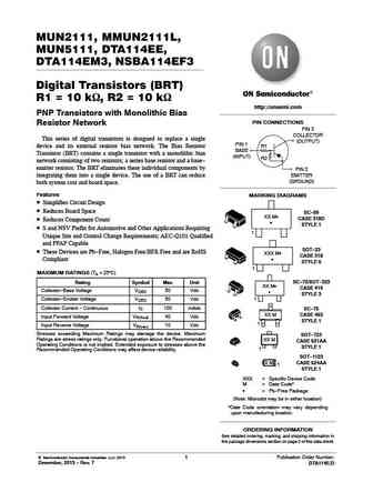
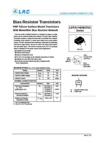
MUN2111, MMUN2111L, MUN5111, DTA114EE, DTA114EM3, NSBA114EF3 Digital Transistors (BRT) R1 = 10 kW, R2 = 10 kW http //onsemi.com PNP Transistors with Monolithic Bias PIN CONNECTIONS Resistor Network PIN 3 COLLECTOR This series of digital transistors is designed to replace a single (OUTPUT) PIN 1 device and its external resistor bias network. The Bias Resistor R1 BASE Transistor (... See More ⇒

MUN2111, MMUN2111L, MUN5111, DTA114EE, DTA114EM3, NSBA114EF3 Digital Transistors (BRT) R1 = 10 kW, R2 = 10 kW http //onsemi.com PNP Transistors with Monolithic Bias PIN CONNECTIONS Resistor Network PIN 3 COLLECTOR This series of digital transistors is designed to replace a single (OUTPUT) PIN 1 device and its external resistor bias network. The Bias Resistor R1 BASE Transistor (... See More ⇒
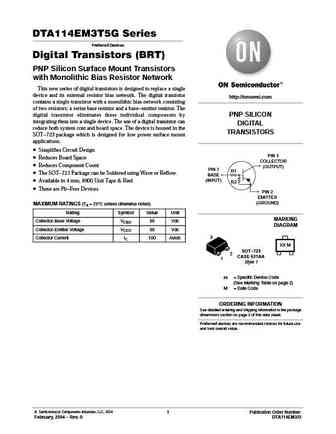

Detailed specifications: DTA113ZVA, DTA114EA3, DTA114EB3, DTA114EEFRA, DTA114EET1G, DTA114EKAFRA, DTA114EM3, DTA114EM3T5G, BC557, DTA114EN3, DTA114ES3, DTA114EUAFRA, DTA114GUA, DTA114TEB, DTA114TEFRA, DTA114TET1G, DTA114TKAFRA
Keywords - DTA114EMFHA pdf specs
DTA114EMFHA cross reference
DTA114EMFHA equivalent finder
DTA114EMFHA pdf lookup
DTA114EMFHA substitution
DTA114EMFHA replacement
