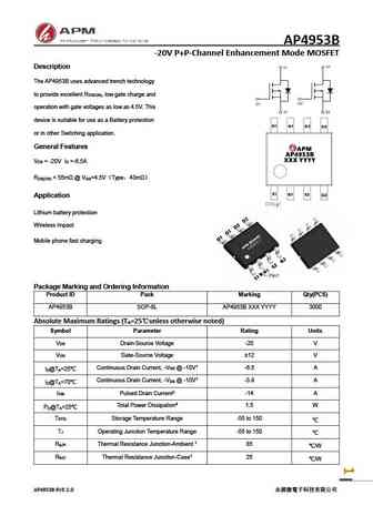
4953B Specs and Replacement
Type Designator: 4953B
Type of Transistor: MOSFET
Type of Control Channel: P-Channel
Absolute Maximum Ratings
Pd ⓘ - Maximum Power Dissipation: 1.5 W
|Vds|ⓘ - Maximum Drain-Source Voltage: 20 V
|Vgs|ⓘ - Maximum Gate-Source Voltage: 10 V
|Id| ⓘ - Maximum Drain Current: 3.5 A
Tj ⓘ - Maximum Junction Temperature: 175 °C
Electrical Characteristics
RDSonⓘ - Maximum Drain-Source On-State Resistance: 0.07 Ohm
Package: SOP8
4953B substitution
- MOSFET ⓘ Cross-Reference Search
4953B datasheet
4953b.pdf
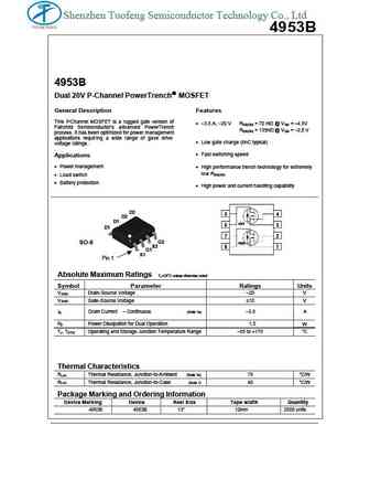
Shenzhen Tuofeng Semiconductor Technology Co., Ltd 4953B 4953B Dual 20V P-Channel PowerTrench MOSFET General Description Features This P MOSFET is a rugged gate version of -Channel 3.5 A, 20 V R = 70 m @ V = 4.5V DS(ON) GS Fairchild Semiconductor s advanced PowerTrench R = 135m @ V = 2.5 .5 V DS(ON) GS process. It has been optimized for power manage... See More ⇒
4953b.pdf
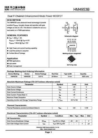
SHENZHEN TUOFENG SEMICONDUCTOR TECHNOLOGY CO.,LTD SOP-8L Dual 20V P-Channel PowerTrench MOSFET 4953B Dual P-Channel 20-V(D-S) MOSFET 4953B V(BR)DSS RDS(on)MAX ID SO-8L D2 D2 0.070 @-4.5V D1 -20V -5.0A D1 0.110 @-2.5V G2 G S2 G1 S S S1 SO-8 S Pin 1 Equivalent Cir cuit General FEATURE 5 4 TrenchFET Power MOSFET Q1 6 3 Lead free product is acquired 7 2 Q2 S... See More ⇒
mtdp4953bdyq8.pdf
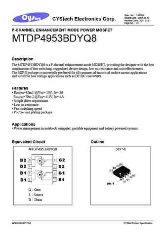
Spec. No. C401Q8 Issued Date 2007.06.13 CYStech Electronics Corp. Revised Date 2011.03.21 Page No. 1/8 P-CHANNEL ENHANCEMENT MODE POWER MOSFET MTDP4953BDYQ8 Description The MTDP4953BDYQ8 is a P-channel enhancement-mode MOSFET, providing the designer with the best combination of fast switching, ruggedized device design, low on-resistance and cost effectiveness. The SO... See More ⇒
jmtp4953b.pdf
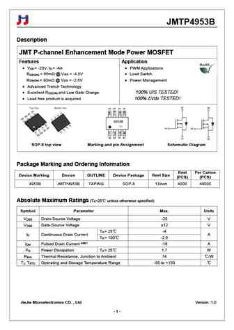
JMTP4953B Description JMT P-channel Enhancement Mode Power MOSFET Features Application V = -20V, I = -4A PWM Applications DS D R ... See More ⇒
Detailed specifications: 4946 , 4953 , 6604 , 8810 , 8820 , 8822 , 9435 , 4953A , CS150N03A8 , 9926A , 9926B , AO3410 , APM2317 , FDMA905 , FDN338 , S8205A , SI2301A .
Keywords - 4953B MOSFET specs
4953B cross reference
4953B equivalent finder
4953B pdf lookup
4953B substitution
4953B replacement
Step-by-step guide to finding a MOSFET replacement. Cross-reference parts and ensure compatibility for your repair or project.
🌐 : EN ES РУ
LIST
Last Update
MOSFET: ASB80R750E | ASB70R380E | ASB65R300E | ASB65R220E | ASB65R120EFD | ASB60R150E | ASA80R900E | ASA80R750E | ASA80R290E | ASA70R950E
Popular searches
2sc1940 | ftp08n06a | 2n3405 | 2n3567 | 2sc1226 | 2sd180 | 2sd235 | k3502 datasheet
