IXFL132N50P3 Specs and Replacement
Type Designator: IXFL132N50P3
Type of Transistor: MOSFET
Type of Control Channel: N-Channel
Absolute Maximum Ratings
Pd ⓘ - Maximum Power Dissipation: 520 W
|Vds|ⓘ - Maximum Drain-Source Voltage: 500 V
|Vgs|ⓘ - Maximum Gate-Source Voltage: 30 V
|Id| ⓘ - Maximum Drain Current: 63 A
Tj ⓘ - Maximum Junction Temperature: 150 °C
Electrical Characteristics
|Vgs(th)|ⓘ - Maximum Gate-Threshold Voltage: 5 V
Qg ⓘ - Total Gate Charge: 250 nC
tr ⓘ - Rise Time: 9 nS
Cossⓘ - Output Capacitance: 1750 pF
Rds ⓘ - Maximum Drain-Source On-State Resistance: 0.043 Ohm
Package: ISOPLUS264
IXFL132N50P3 substitution
- MOSFET ⓘ Cross-Reference Search
IXFL132N50P3 datasheet
ixfl132n50p3.pdf
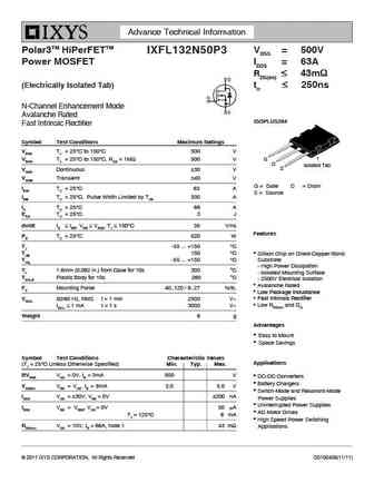
Advance Technical Information Polar3TM HiPerFETTM VDSS = 500V IXFL132N50P3 Power MOSFET ID25 = 63A RDS(on) 43m (Electrically Isolated Tab) trr 250ns N-Channel Enhancement Mode Avalanche Rated ISOPLUS264 Fast Intrinsic Rectifier Symbol Test Conditions Maximum Ratings VDSS TJ = 25 C to 150 C 500 V G VDGR TJ = 25 C to 15... See More ⇒
ixfl100n50p.pdf
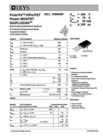
IXFL 100N50P VDSS = 500 V PolarHVTM HiPerFET ID25 = 70 A Power MOSFET RDS(on) 52 m ISOPLUS264TM trr 200 ns (Electrically Isolated Back Surface) N-Channel Enhancement Mode Avalanche Rated Fast Intrinsic Diode ISOPLUS264 Symbol Test Conditions Maximum Ratings VDSS TJ = 25 C to 150 C 500 V VDGR TJ = 25 C to 1... See More ⇒
Detailed specifications: IXFP14N60P3 , IXFN94N50P2 , IXFN55N50F , IXFN40N110Q3 , IXFN260N17T , IXFN210N30P3 , IXFN200N06 , IXFL210N30P3 , 2SK3878 , IXFK90N60X , IXFK32N90P , IXFK30N50Q , IXFK260N17T , IXFK24N100Q3 , IXFK210N17T , IXFK150N30P3 , IXFK120N65X2 .
Keywords - IXFL132N50P3 MOSFET specs
IXFL132N50P3 cross reference
IXFL132N50P3 equivalent finder
IXFL132N50P3 pdf lookup
IXFL132N50P3 substitution
IXFL132N50P3 replacement
Can't find your MOSFET? Learn how to find a substitute transistor by analyzing voltage, current and package compatibility
🌐 : EN ES РУ

LIST
Last Update
MOSFET: HAF1008S | HAF1008L | EMZB08P03H | CS30N20FA9R | AOT66613L | AOSP21313C | AOSP21311C | AOB66918L | AO3415C | AOTF20N40L
Popular searches
a1941 | 2sd424 datasheet | 2sc536 datasheet | bd140 transistor equivalent | tip122 transistor equivalent | irfz44n equivalent | 2n2923 | 2n2102