DTB113EK Datasheet. Specs and Replacement
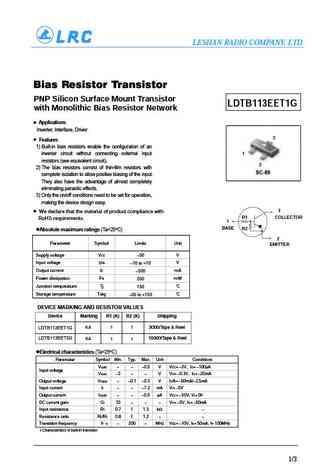
Type Designator: DTB113EK
SMD Transistor Code: F11
Material of Transistor: Si
Polarity: Pre-Biased-PNP
Built in Bias Resistor R1 = 1 kOhm
Built in Bias Resistor R2 = 1 kOhm
Typical Resistor Ratio R1/R2 = 1
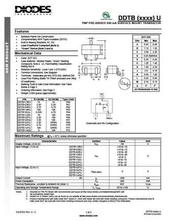
Absolute Maximum Ratings
Maximum Collector Power Dissipation (Pc): 0.2 W
Maximum Collector-Emitter Voltage |Vce|: 50 V
Maximum Emitter-Base Voltage |Veb|: 10 V
Maximum Collector Current |Ic max|: 0.5 A
Max. Operating Junction Temperature (Tj): 150 °C
Electrical Characteristics
Transition Frequency (ft): 140 MHz
Forward Current Transfer Ratio (hFE), MIN: 33
DTB113EK Substitution
- BJT ⓘ Cross-Reference Search
DTB113EK datasheet
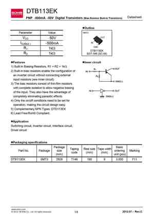
DTB113EK Datasheet PNP -500mA -50V Digital Transistors (Bias Resistor Built-in Transistors) lOutline SMT3 Parameter Value OUT VCC -50V IN IC(MAX.) -500mA GND R1 1kW DTB113EK R2 1kW SOT-346 (SC-59) lFeatures lInner circuit 1) Built-In Biasing Resistors, R1 = R2 = 1kW. 2) Built-in bias resistors enable the configuration of an inverter circuit without connecting externa... See More ⇒
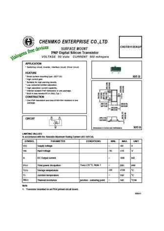
CHENMKO ENTERPRISE CO.,LTD CHDTB113EKGP SURFACE MOUNT PNP Digital Silicon Transistor VOLTAGE 50 Volts CURRENT 500 mAmpere APPLICATION * Switching circuit, Inverter, Interface circuit, Driver circuit. FEATURE * Small surface mounting type. (SOT-23) SOT-23 * High current gain. * Suitable for high packing density. * Low colloector-emitter saturation. * High saturation current capabil... See More ⇒
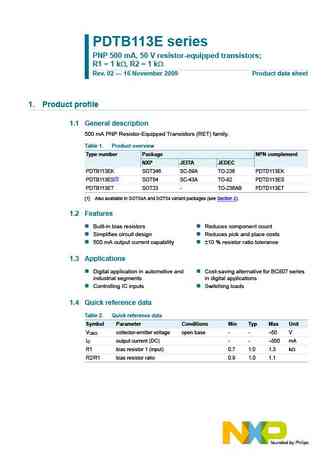
PDTB113E series PNP 500 mA, 50 V resistor-equipped transistors; R1 = 1 k , R2 = 1 k Rev. 02 16 November 2009 Product data sheet 1. Product profile 1.1 General description 500 mA PNP Resistor-Equipped Transistors (RET) family. Table 1. Product overview Type number Package NPN complement NXP JEITA JEDEC PDTB113EK SOT346 SC-59A TO-236 PDTD113EK PDTB113ES[1] SOT54 SC-43A TO-92 PDT... See More ⇒
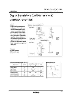
DTB113EK / DTB113ES Transistors Digital transistors (built-in resistors) DTB113EK / DTB113ES Feature External dimensions (Unit mm) 1) Built-in bias resistors enable the + 2.9 0.2 - DTB113EK 1.1+0.2 configuration of an inverter circuit + -0.1 1.9 0.2 - + without connecting external input 0.8 0.1 0.95 0.95 - resistors (see equivalent circuit). (1) (2) 0 0.1 2... See More ⇒
Detailed specifications: DTA144TUA, DTA144VKA, DTA144VSA, DTA144VUA, DTC115TS3, DTA144WKA, DTA144WSA, DTA144WUA, C1815, DTB113ES, DTB114EK, DTB114ES, DTB123EK, DTB123ES, DTB143EC, DTB143EK, DTB143ES
Keywords - DTB113EK pdf specs
DTB113EK cross reference
DTB113EK equivalent finder
DTB113EK pdf lookup
DTB113EK substitution
DTB113EK replacement
