ST41 Specs and Replacement
Type Designator: ST41
Material of Transistor: Si
Polarity: NPN
Absolute Maximum Ratings
Maximum Collector Power Dissipation (Pc): 0.2 W
Maximum Collector-Base Voltage |Vcb|: 45 V
Maximum Collector-Emitter Voltage |Vce|: 35 V
Maximum Emitter-Base Voltage |Veb|: 2 V
Maximum Collector Current |Ic max|: 0.025 A
Max. Operating Junction Temperature (Tj): 200 °C
Electrical Characteristics
Transition Frequency (ft): 5 MHz
Forward Current Transfer Ratio (hFE), MIN: 30
Package: TO5
ST41 Substitution
- BJT ⓘ Cross-Reference Search
ST41 datasheet
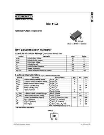
KST4123 General Purpose Transistor 3 2 SOT-23 1 1. Base 2. Emitter 3. Collector NPN Epitaxial Silicon Transistor Absolute Maximum Ratings Ta=25 C unless otherwise noted Symbol Parameter Value Units VCBO Collector-Base Voltage 40 V VCEO Collector-Emitter Voltage 30 V VEBO Emitter-Base Voltage 5 V IC Collector Current 200 mA PC Collector Power Dissipation 350 mW TSTG Storage Temp... See More ⇒
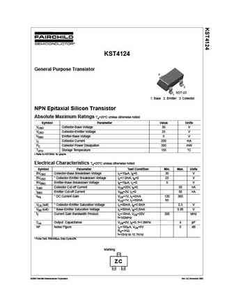
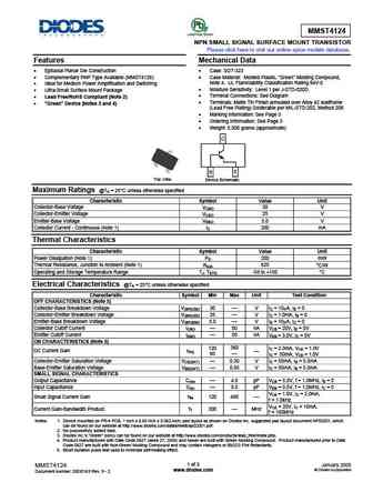
KST4124 General Purpose Transistor 3 2 SOT-23 1 1. Base 2. Emitter 3. Collector NPN Epitaxial Silicon Transistor Absolute Maximum Ratings Ta=25 C unless otherwise noted Symbol Parameter Value Units VCBO Collector-Base Voltage 30 V VCEO Collector-Emitter Voltage 25 V VEBO Emitter-Base Voltage 5 V IC Collector Current 200 mA PC Collector Power Dissipation 350 mW TSTG Storage Temp... See More ⇒
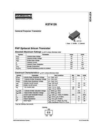
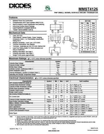
KST4126 General Purpose Transistor 3 2 SOT-23 1 1. Base 2. Emitter 3. Collector PNP Epitaxial Silicon Transistor Absolute Maximum Ratings Ta=25 C unless otherwise noted Symbol Parameter Value Units VCBO Collector-Base Voltage -25 V VCEO Collector-Emitter Voltage -25 V VEBO Emitter-Base Voltage -4 V IC Collector Current -200 mA PC Collector Power Dissipation 350 mW TSTG Storage ... See More ⇒
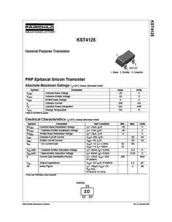
KST4125 General Purpose Transistor 3 2 SOT-23 1 1. Base 2. Emitter 3. Collector PNP Epitaxial Silicon Transistor Absolute Maximum Ratings Ta=25 C unless otherwise noted Symbol Parameter Value Units VCBO Collector-Base Voltage -30 V VCEO Collector-Emitter Voltage -30 V VEBO Emitter-Base Voltage -4 V IC Collector Current -200 mA PC Collector Power Dissipation 350 mW TSTG Storage ... See More ⇒
Detailed specifications: ST3906, ST40, ST400, ST401, ST4044, ST4045, ST4080, ST4081, S8550, ST410, ST411, ST414, ST4150, ST42, ST4201, ST4202, ST4203
Keywords - ST41 pdf specs
ST41 cross reference
ST41 equivalent finder
ST41 pdf lookup
ST41 substitution
ST41 replacement
