MMBT720 Datasheet. Specs and Replacement
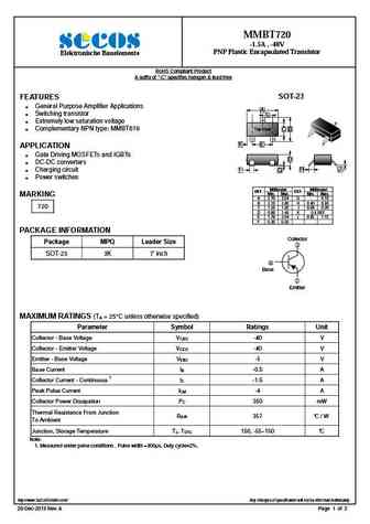
Type Designator: MMBT720 📄📄
SMD Transistor Code: 720
Material of Transistor: Si
Polarity: PNP
Absolute Maximum Ratings
Maximum Collector Power Dissipation (Pc): 0.35 W
Maximum Collector-Base Voltage |Vcb|: 40 V
Maximum Collector-Emitter Voltage |Vce|: 40 V
Maximum Emitter-Base Voltage |Veb|: 5 V
Maximum Collector Current |Ic max|: 1.5 A
Max. Operating Junction Temperature (Tj): 150 °C
Electrical Characteristics
Transition Frequency (ft): 150 MHz
Collector Capacitance (Cc): 25 pF
Forward Current Transfer Ratio (hFE), MIN: 12
Package: SOT-23
MMBT720 Substitution
- BJT ⓘ Cross-Reference Search
MMBT720 datasheet
MMBT720 -1.5A , -40V PNP Plastic Encapsulated Transistor Elektronische Bauelemente RoHS Compliant Product A suffix of -C specifies halogen & lead-free SOT-23 FEATURES General Purpose Amplifier Applications A Switching transistor L 3 Extremely low saturation voltage 3 Complementary NPN type MMBT619 Top View C B 1 1 2 2 K E APPLICATION Gate Driving MOSFE... See More ⇒
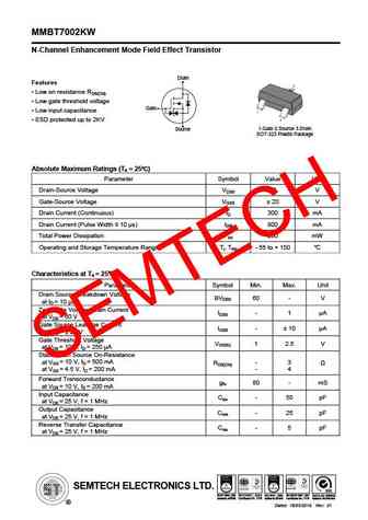
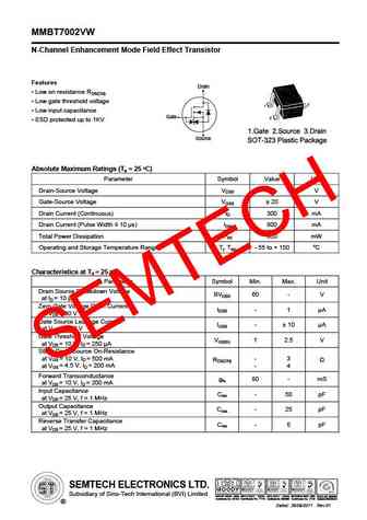
MMBT7002KW N-Channel Enhancement Mode Field Effect Transistor Drain Features Low on resistance RDS(ON) Low gate threshold voltage Gate Low input capacitance ESD protected up to 2KV 1.Gate 2.Source 3.Drain Source SOT-323 Plastic Package Absolute Maximum Ratings (Ta = 25 ) Parameter Symbol Value Unit Drain-Source Voltage VDSS 60 V Gate-Source Voltage VGSS ... See More ⇒
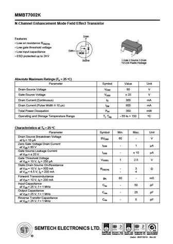
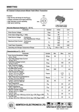
MMBT7002K N-Channel Enhancement Mode Field Effect Transistor Drain Features Low on resistance RDS(ON) Low gate threshold voltage Gate Low input capacitance ESD protected up to 2KV 1.Gate 2.Source 3.Drain Source TO-236 Plastic Package O Absolute Maximum Ratings (Ta = 25 C) Parameter Symbol Value Unit Drain-Source Voltage VDSS 60 V Gate-Source Voltage VGSS ... See More ⇒
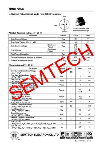
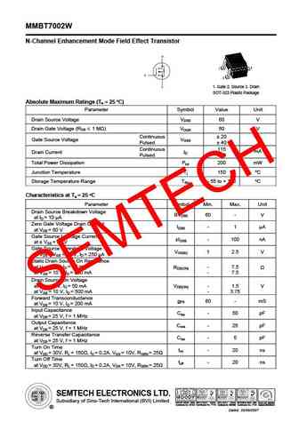
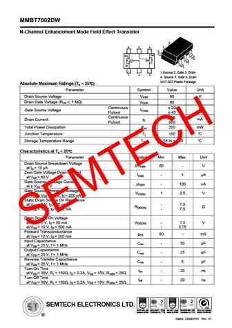
MMBT7002E N-Channel Enhancement Mode Field Effect Transistor Drain Gate 1. Gate 2. Source 3. Drain SOT-523 Plastic Package Source O Absolute Maximum Ratings (Ta = 25 C) Parameter Symbol Value Unit Drain Source Voltage VDSS 60 V Drain Gate Voltage (RGS 1 M ) VDGR 60 V Continuous 20 V Gate Source Voltage VGSS Pulsed 40 Continuous 115 mA Drain Current ID ... See More ⇒
Detailed specifications: MMBT6427LT1G, MMBT6428LT1, MMBT6428LT1G, MMBT6429LT1G, MMBT6515, MMBT6517LT1G, MMBT6520LT1G, MMBT6521LT1G, BC548, MMBT8050, MMBT8050D, MMBT8050LT1, MMBT8099LT1G, MMBT8550, MMBT8550LT1, MMBT9012LT1, MMBT9013LT1
Keywords - MMBT720 pdf specs
MMBT720 cross reference
MMBT720 equivalent finder
MMBT720 pdf lookup
MMBT720 substitution
MMBT720 replacement
