IRF9388PBF Datasheet. Specs and Replacement
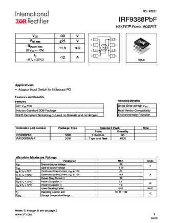
Type Designator: IRF9388PBF 📄📄
Type of Transistor: MOSFET
Type of Control Channel: P-Channel
Absolute Maximum Ratings
Pd ⓘ - Maximum Power Dissipation: 2.5 W
|Vds|ⓘ - Maximum Drain-Source Voltage: 30 V
|Vgs|ⓘ - Maximum Gate-Source Voltage: 25 V
|Id| ⓘ - Maximum Drain Current: 12 A
Tj ⓘ - Maximum Junction Temperature: 150 °C
Electrical Characteristics
tr ⓘ - Rise Time: 57 nS
Cossⓘ - Output Capacitance: 350 pF
RDSonⓘ - Maximum Drain-Source On-State Resistance: 0.0119 Ohm
Package: SO-8
📄📄 Copy
IRF9388PBF substitution
- MOSFET ⓘ Cross-Reference Search
IRF9388PBF datasheet
irf9388pbf.pdf
PD - 97521 IRF9388PbF HEXFET Power MOSFET VDS -30 V VGS max 25 V RDS(on) max 11.9 m (@VGS = -10V) ID -12 A (@TA = 25 C) SO-8 Applications Adaptor Input Switch for Notebook PC Features and Benefits Resulting Benefits Features 25V VGS max Direct Drive at High VGS Industry-Standard SO8 Package Multi-Vendor Compatibility Environmentally Friendlier RoHS Compliant... See More ⇒
irf9389pbf.pdf
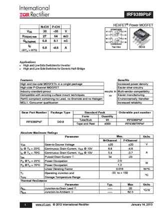
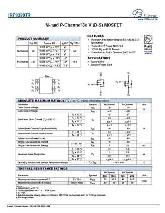
IRF9389PbF HEXFET Power MOSFET N-CH P-CH N-CHANNEL MOSFET 1 8 S1 D1 VDS 30 -30 V 2 7 G1 D1 RDS(on) max 27 64 m 3 6 S2 D2 Qg (typical) 6.8 8.1 nC 4 5 G2 D2 P-CHANNEL MOSFET ID Top View SO-8 6.8 -4.6 A (@TA = 25 C) Applications l High and Low Side Switches for Inverter l High and Low Side Switches for Generic Half-Bridge Features Benefits High and low-side MOSFETs i... See More ⇒
irf9389.pdf
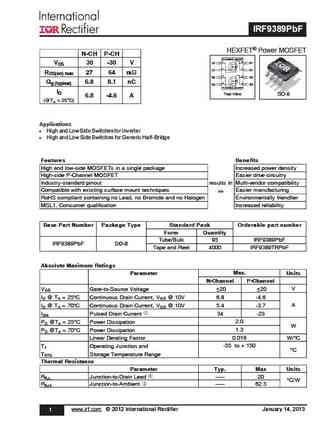
IRF9389PbF HEXFET Power MOSFET N-CH P-CH N-CHANNEL MOSFET 1 8 S1 D1 VDS 30 -30 V 2 7 G1 D1 RDS(on) max 27 64 m 3 6 S2 D2 Qg (typical) 6.8 8.1 nC 4 5 G2 D2 P-CHANNEL MOSFET ID Top View SO-8 6.8 -4.6 A (@TA = 25 C) Applications l High and Low Side Switches for Inverter l High and Low Side Switches for Generic Half-Bridge Features Benefits High and low-side MOSFETs i... See More ⇒
irf9383mpbf.pdf
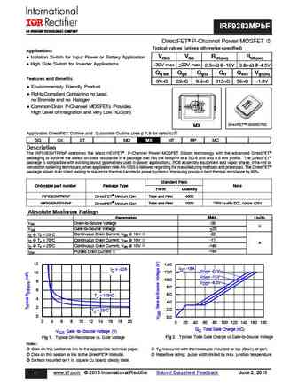
IRF9383MPbF DirectFET P-Channel Power MOSFET Typical values (unless otherwise specified) Applications l Isolation Switch for Input Power or Battery Application VDSS VGS RDS(on) RDS(on) l High Side Switch for Inverter Applications -30V max 20V max 2.3m @-10V 3.8m @-4.5V Qg tot Qgd Qgs2 Qrr Qoss Vgs(th) Features and Benefits 67nC 29nC 9.4nC 315nC 59nC -1.8V l Environmentaly ... See More ⇒
Detailed specifications: IRF9321PBF, IRF9328PBF, IRF9332PBF, IRF9333PBF, IRF9335PBF, IRF9358PBF, IRF9362PBF, IRF9383MPBF, IRF640N, IRF9389, IRF9392PBF, IRF9393PBF, IRF9395MPBF, IRF9410PBF, IRF9510SPBF, IRF9520NLPBF, IRF9520S
Keywords - IRF9388PBF MOSFET specs
IRF9388PBF cross reference
IRF9388PBF equivalent finder
IRF9388PBF pdf lookup
IRF9388PBF substitution
IRF9388PBF replacement
Learn how to find the right MOSFET substitute. A guide to cross-reference, check specs and replace MOSFETs in your circuits.
MOSFET Parameters. How They Affect Each Other
History: IRF9393PBF
🌐 : EN ES РУ
LIST
Last Update
MOSFET: BC3134KT | BC3134K | BC2302W | BC2302T-2.8A | BC2302-2.8A | BC2301W | BC2301T-2.8A | CB3139KTB | CB2301DW | BC8205
Popular searches
2sc1735 | transistor 2sc5200 | 2sb560 transistor | a1273 | c3421 transistor | c644 transistor | fgpf4536 datasheet | p20nm60fp datasheet
